Table of Contents
Advertisement
Advertisement
Table of Contents

Related Manuals for Triax TDX


Summary of Contents for Triax TDX
- Page 1 Contents User guide TDX Headend Unit - Art. No. 492090 │ EN│ 891072I...
-
Page 2: Table Of Contents
Contents Contents SAFETY PRECAUTIONS ..............................4 Environment ................................4 Power supply ................................4 Weight ..................................4 Earth ................................... 4 Disposal ..................................4 INTRODUCTION ................................. 5 ................................. 5 OX CONTENTS HEADEND OVERVIEW ..............................6 ..................................6 XTERIOR ..................................7 NTERIOR SINGLE HEADEND INSTALLATION ..........................8 .................................. - Page 3 Contents SERVICE TOOL ................................23 ..............................23 YSTEM REQUIREMENTS Computer minimum requirements ..........................23 Static IP address ..............................23 Physical connection to headend..........................23 Starting Service tool ..............................24 ..................................25 VERVIEW ADMINISTRATION ................................27 ..................................27 ANGUAGE ..................................28 OCATION ..................................
-
Page 4: Safety Precautions
Safety Safety Precautions Environment Operating temperature -10 C to +50 C. Storage temperature -20 C to + 70 C. Max. Operating humidity 80% (RH). Max. Storage humidity 90% (RH). Power supply The input voltage must be 190-264 VAC. ~ 45/65 Hz / 280 W (Max). Use only power connections installed by professionals. -
Page 5: Introduction
Headend Overview Introduction The TDX cabinet is designed to accommodate up to 16 input modules and 6 quad output modules. Up to three TDX headends can be combined as one system of up to 48 input muxes and 72 output channels. -
Page 6: Headend Overview
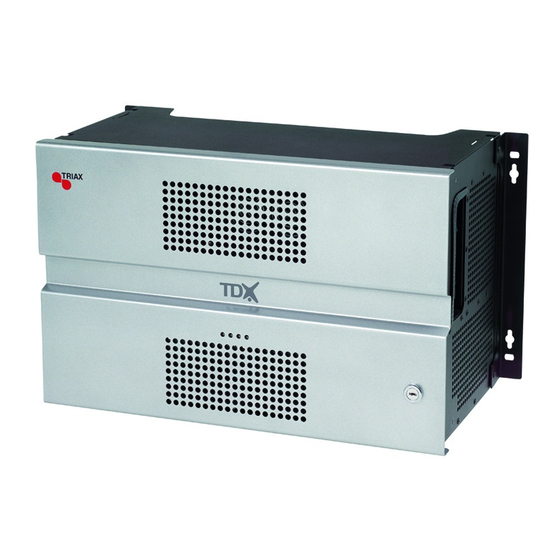
Headend Overview Headend overview Exterior A Input module area B Output module area C Mounting brackets D Lock Headend status LEDs... -
Page 7: Interior
Headend Overview Interior Input slots (16 in total) Extractor fans Earth terminal Power input RF output Distributes the RF channels from the output modules using an F-connector. Test point -20 dB RF test point of output (-20 dB). Configuration port Ethernet configuration port for setting up the headend unit. -
Page 8: Single Headend Installation
Headend Installation Single headend installation The headend can be mounted either on a system rack or directly onto Mounting a wall. Rack installation Wall installation 1. Attach the mounting brackets to the headend with the supplied screws. Installation Bracket position Rack At the front of a headend. -
Page 9: Power/Earth
Headend Installation 1. Connect an earth cable to the Earth terminal. Power/Earth 2. Attach the other end of the earth cable to an approved „earth‟ connection point. 3. Insert the supplied cable into the Power Input port. Confirm that the ID Switch is set to "0". ID switch... -
Page 10: Multi Headend Installation
Headend Installation Multi headend installation Up to three headends can be combined to further increase the number of services provided. The headends are physically installed as per installation of single headend, i.e. by using the supplied brackets described above. Ensure that the following ventilation requirements are met: Ventilation requirements Horizontal... -
Page 11: Connecting Units - Direct Connection
Headend Installation Connecting units – Direct connection Note that direct connection hardware configurations require the Connection type field in the service tool‟s Admin/IP Settings/Setup window to be set to „Direct‟. 1xMain – 1xSub Main Unit Link1 Link2 Link1 Link2 Subunit 1. -
Page 12: 1Xmain - 2Xsub
Headend Installation 1xMain – 2xSub Main Unit Link1 Link2 Link1 Link2 Subunit 1 Link1 Link2 Subunit 2 1. Insert SFP copper transceivers into the “Link 1“ and “Link 2” sockets on the main headend and subunit headends. 2. Route a RJ45 Cat5e or better cable from the "Link 1" socket on the main unit to the "Link 1"... -
Page 13: Rf Output
Connection type field in the service tool‟s Admin /IP Settings /Setup window to be set to Switch. Triax recommends that a network switch is used for connecting the main and subunits even if IP services are not currently supported. The network switch used must support IGMP ver. -
Page 14: Multi Headend Installation - Fiber Optic
Fiber-optic cables must be used to connect the main headend unit to one or two subunits over distances greater than 100m. The following SFP fibre-optic transceivers must be used in the Link sockets: Triax Art. Type Data rate Reach Application 492087... -
Page 15: Input Modules
Input Modules Input modules 16 input modules can be installed per headend unit. Hot swap technology is used in the headend, meaning that modules can be inserted/removed/moved when the headend is in operation. Input module types Each input module is identified through the use of a specifically coloured label. -
Page 16: Inserting Input Modules
Input Modules Inserting input 1. Prize the protective cover away from modules an available input slot. 2. Retain the protective cover. Note: Any available input slot can be used. 3. Push the input module into the input slot until the input module is locked in position. -
Page 17: Looping Cables
Input Modules Note: Ensure that enough cable is available for relocating input modules to alternate input slots at a later date. Looping cables DVB-S/S2 signals can be looped between input modules: 1. Attach the signal cable to the IN port on one DVB-S/S2 input module. -
Page 18: Output Modules
Output Modules Six output modules, each consisting of four RF channels can be Output modules installed in a headend unit. Hot Flash technology is used in the headend, meaning that output modules can be inserted/removed/moved while the headend is running. Output module types Each output module is identified through use of a specifically coloured label. -
Page 19: Inserting Output Module
Output Modules Inserting output Depending on where you want to insert the output module push module the extractor fan to the opposite side. 1. Insert smart cards (if relevant). Insert the service provider‟s smartcard into the CA module. Insert the CA module into either of the available slots in the output module. -
Page 20: System Monitoring
System Monitoring System Monitoring Four LEDs are placed at the top of the output section of each headend LEDs unit, and provide information on the state of the headend and subunits (if present). The four LEDs are named (from left to right): System Status Tuner Status Unit Link 1... - Page 21 System Monitoring Green – flashing installation The headend is booting up. An error has been detected in the headend, which must be investigated. Green – Tuner The input module tuners are locked. Status constant One or more Input module tuners are not locked.
- Page 22 System Monitoring There is a problem with the connection to the subunit. No colour No subunit is connected to the main unit. Green – Unit Link 2 The subunit is connected to the main unit. constant There is a problem with the connection to the subunit.
-
Page 23: Service Tool
Service Tool Service tool The headend needs to be configured before it can be used. System requirements Computer minimum A computer meeting the following minimum requirements is required requirements for configuring the headend. Operating system: Windows XP or above Browser: Windows Internet Explorer version 6.0 or equivalent Additional software: Microsoft©... -
Page 24: Starting Service Tool
Service Tool Starting Service tool 1. Open a web browser window. 2. Enter ‘http://192.168.0.100‟ in the web address field. 3. Press Enter. 4. Enter the password. 5. Press the Log in button. Note: Password = „triax1234’ when the service tool is opened on each headend for the first time. -
Page 25: Overview
General Settings Administration Overview Communication icon Tabs Misc. Buttons System icons Configuration buttons Communication icon Indicates whether the service tool is communicating correctly with the headend unit. Green The service tool and headend are communicating correctly. The service tool and headend are NOT communicating correctly. - Page 26 General Settings Administration Accesses the various tabs used to configure the headend‟s input and Tabs output modules. The service tool‟s „home‟ window. Provides system System overview information and configuration activation/control. Input Tab for configuring input modules and services. CA Modules Tab for configuring CI modules and CA cards.
-
Page 27: Administration
General Settings Administration Administration The system language, locale, and time zone need to be specified on each headend unit. It is also necessary to specify IP addresses for headends which are located on a distribution network. Language 1. Press the Admin button at the top right-hand corner of the System window. -
Page 28: Location
General Settings Administration Location 1. Press the Admin button at the top right-hand corner of the System window. 2. Expand the Country settings area. 3. Open the Current location drop-down list. 4. Select the country where the headend is located. 5. - Page 29 General Settings Administration Time zone 1. Press the Admin button at the top right-hand corner of the System window. 2. Expand the Time zone settings area. 3. Open the Input module (Main unit) drop-down list. 4. Select the input module that is to be used for setting the headend‟s system date/time/time zone.
-
Page 30: Security
General Settings Administration Security 1. Press the Admin button at the top right-hand corner of the System window. 2. Expand the Password settings area. 3. Specify the current password in the Old password field. („triax1234’) if the service tool is being used for the first time. 4. -
Page 31: Licences
2. Expand the Licence handling area. 3. Contact Triax Sales and provide the contents of the serial number and unique ID fields. 4. Enter the code provided by Triax Sales into the Activation key field. 5. Press the Activate button. -
Page 32: Ip Addresses
General Settings Administration It may be necessary to specify specific IP addresses for the headend to IP addresses avoid network IP address conflicts. Note: Headend IP addresses can be reset to factory default settings if required. This is done via the ID switch located on the headend unit(s). 1. - Page 33 General Settings Administration The IP Settings window is used to specify unique IP addresses and subnet masks used by the Link 1 and Link 2 sockets on the main and sub units. This provides additional functionality to avoid IP address conflicts.
- Page 34 General Settings Administration A message is displayed if the headend needs to be rebooted due to IP address changes having been made.
-
Page 35: Snmp Settings
General Settings Administration SNMP stands for “Simple Network Management Protocol”. SNMP settings SNMP is an Internet standard protocol that you use for exchanging management information between the equipment in a CATV network. You can use SNMP to monitor sub-headends, fibre notes and amplifiers or to check the status of the equipment. -
Page 36: Rebooting
General Settings Administration Rebooting 1. Press the Admin button at the top of the right-hand corner of the System window. 2. Expand the System maintenance area. 3. Press the Reboot button. Note: Changes to IP addresses only take effect when the headend has been rebooted. -
Page 37: Viewing System Log
General Settings Administration It is possible to save log files for viewing headend actions. Viewing system 1. Press the Admin button at the top of the right-hand corner of the System window. - Page 38 General Settings Administration 2. Expand the System maintenance area. 3. Press the Save log button. 4. Press Open to view the log file in notepad. 5. Press Save to specify a file location and if required rename the log file as per normal Windows operating system procedure.
-
Page 39: Firmware
General Settings Administration Firmware Updating Firmware updates are available from the Triax home page, www.Triax.com. Always read the release notes to determine whether the headend would benefit from available firmware updates or not. 1. Press the Admin button at the top of the right-hand corner of the System window. - Page 40 General Settings Administration 4. Press the Upload file button. 5. Navigate to where the update file is saved. 6. Select the file. 7. Press the Open button. The new firmware update file is listed in the Change firmware dialog. 8. Check the Active check box for the new update file. 9.
- Page 41 General Settings Administration 10. Select the Replace all radio button to update all of the headend‟s firmware, i.e. modules, system controller and user interface. (Recommended) 11. Select the Update old packages radio button to only update outdated modules. 12. Press the Start update button. Note: The Update old packages radio button should only be used in cases where the headend consists mainly of new modules, but also contains...
-
Page 42: Cleaning Up
General Settings Administration 14. Restart the internet browser when prompted. 15. Logon to the system tool and make any further changes. Cleaning up 1. Select the firmware updates to be removed from the system tool. 2. Press the Delete package button. -
Page 43: System Information
General Settings Administration System Information Detailed information is available on headend units: Viewing System information 1. Select the System tab. 2. Select the main unit or one of the subunits in the System information list area. The System information for unit window is displayed. The window contains information relating to: ... -
Page 44: Duplicated Pids
General Settings Administration Update the software for the entire headend installation (including input/output modules) if this is not the case. MAC addresses Current/minimum/maximum temperatures Power supply Selecting IP services for output may result in a selection of services from Duplicated PIDs an MPTS stream that uses the same PID for two or more services. -
Page 45: Managing Configuration Files
Managing Configuration Files Managing configuration files 1. Select the System window. Creating 2. Select the New button. An empty configuration file is created and listed in the configuration list area. Activating 1. Select the System tab. 2. Select the configuration that is to be actively used on the headend. -
Page 46: Uploading
Managing Configuration Files 1. Select the System tab. 2. Press the Load from TDX button. 3. Navigate to where the configuration file is to be saved. 4. Enter a name for the configuration file. 5. Select „XML‟ in the File type field. - Page 47 Managing Configuration Files 2. Press the Load to TDX button. 3. Navigate to the folder where the configuration file to be uploaded is located. 4. Select the file. 5. Press the Open button. The configuration file will now be listed in the configuration list area. A number in brackets, e.g.
-
Page 48: Ip Input Configurations
IGMP version 2 SPTS or MPTS including PAT, PMT, CAT Important: The TDX headend system supports up to 7 TS packets per IP packet at IP inputs. The TDX headend system does not support IP fragmentation at... -
Page 49: Creating
IP Input Configurations Creating 1. Select the Input tab. 2. Select the IP inputs sub-tab. 3. Press the Setup button for the link socket that processes IP input. 4. Specify the desired IP address and associated IP port number in the corresponding fields. 5. - Page 50 IP Input Configurations Important: If the IP input uses MPTS streams, then each stream can contain one or more services. An MPTS stream may use the same PID (Package ID) for two or more of the services that it contains. However, the headend system cannot output services with the same PID.
- Page 51 IP Input Configurations Specifying EIT/EPG source One input on each link per headend can be configured to carry Event Information Table (EIT) data. 1. Specify the desired IP address and associated IP port number in the corresponding fields. 2. Check the Use as EIT input checkbox. 3.
- Page 52 IP Input Configurations Specifying Alternative EIT/EPG source 1. Specify the desired IP address and associated IP port number in the corresponding fields. 2. Open the Alternative EIT source drop-down list. 3. Select the EIT source to be used. 4. Press the Update button. 5.
-
Page 53: Modifying
IP Input Configurations To modify an existing IP input configuration: Modifying 1. Press the Setup button associated with the IP input configuration. 2. Make the required modifications as when creating an IP input configuration. 3. Press the Submit button. 4. Press the Apply button when the modifications have been made. -
Page 54: Ip Output Configurations
Not possible to change service ID (SID) Note: Licenses for IP output are required to be able to use the IPTV functionality in the headend. The licenses can be purchased from Triax Sales, and need to be activated, see “Activating licenses”. 1. Select the Output tab. - Page 55 IP Output Configurations 4. Specify the desired IP address and associated IP port number in the corresponding fields. 5. Press the Services button. The Select Services window displays services from input that has entered the headend system through the same unit which contains the Link socket(s) being used for service distribution.
- Page 56 IP Output Configurations using the Link sockets. They can, however, be distributed using an IP output module and the AUX sockets. See the IP output module user guide for further information. 8. View the Status information area to see the following: ...
-
Page 57: License Limitations
IP Output Configurations License limitations The following message is displayed if more services have been selected than are permitted by the current licenses. To modify and existing IP output configurations: Modifying 1. Press the Setup button associated with the IP output configuration. -
Page 58: Eit/Epg Output
IP Output Configurations EIT/EPG output If you want to distribute EIT information in connection with your IP output, you can choose between: distributing EIT information with every single IP service, or use a barker channel for carrying all EIT information for the IP output. -
Page 59: Eit - Barker Channel
IP Output Configurations 2. Open the EIT drop-down list. 3. Select “Full Actual – No other”. 4. Press the Submit button. A message window is displayed confirming that the configuration has been submitted. 5. Press the Apply button. EIT – barker 1. - Page 60 IP Output Configurations Note: The IP address used for the barker channel must not conflict with any of the IP addresses used for service distribution. A message window is displayed confirming that the configuration has been submitted. 7. Press the Apply button. The Network window now contains a single line of information stating which unit and socket is used by the EIT barker channel.
-
Page 61: Snmp Traps
Trap generated when an input module has an error, e.g. module no longer locked to frequency, missing module etc, CIInsertion OID: 1.3.6.1.4.1.41359.1.1.1.8 Trap generated when a CI module is inserted in the TDX. CIRemoval 1.3.6.1.4.1.41359.1.1.1.9 Trap generated when a CI module is removed from the TDX. - Page 62 ModuleInsertion 1.3.6.1.4.1.41359.1.1.1.10 Trap generated when an input or output module is inserted. ModuleRemoval 1.3.6.1.4.1.41359.1.1.1.11 Trap generated when an input or output module is removed. CIDescramblingError 1.3.6.1.4.1.41359.1.1.1.12 Trap generated when a service descrambling has an error. CICommunicationDown 1.3.6.1.4.1.41359.1.1.1.13 Trap generated when communication with CI module fails. VideoDecodingError 1.3.6.1.4.1.41359.1.1.1.14 Trap generated when video decoding of a service in a PAL output module fails.
- Page 63 CICommunicationUP 1.3.6.1.4.1.41359.1.1.1.19 Trap generated when communication with the CI module no longer fails. VideoDecodingOK 1.3.6.1.4.1.41359.1.1.1.20 Trap generated when a video decoding of a service in PAL output module no longer fails. InterlinkConnect 1.3.6.1.4.1.41359.1.1.1.21 Trap generated when a main unit is connected to a subunit...
- Page 64 8783 Hornsyld web: www.triax.dk Denmark DECLARATION OF CONFORMITY TRIAX confirms that the product conforms to relevant EEC harmonised standards and consequently can carry the CE-mark. Relevant harmonised standards: DE/EN 60728-2 2010, DS/EN 60728-11 2010 and DS/EN 50083-2 2006 This document is only valid with the signature of the person responsible for CE-marking by...
Need help?
Do you have a question about the TDX and is the answer not in the manual?
Questions and answers