Table of Contents
Advertisement
Quick Links
Advertisement
Table of Contents

Related Manuals for Whirlpool G0


Summary of Contents for Whirlpool G0
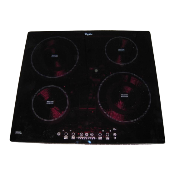
- Page 1 Induction cooktop G0 Induction G0 © Service Competence Center...
- Page 2 Induction cooktop G0 Chapter List Induction G0 Table of Contents Installation Operation Components Repair guide line Troubleshooting Marketing information Version 1.1 © Service Competence Center...
- Page 3 Table of Contents Installation Components Exploded view Dimensions 60 cm Overview components Dimensions 77 cm Overview converter board Standard Installation ESAM connection Full integrated installation Overview cable connection Electric connection ...
- Page 4 Failure code type 3 Accessories Failure description LED and buzzer check Access main menu Main menu Configuration G0 Failure Show Delete Failures Test program rules Configuration Codes Wiring diagram ©...
- Page 5 Installation Dimensions 60 cm Dimensions 77 cm Standard Installation Full integrated installation Electrical connection © Service Competence Center...
- Page 6 Installation Dimensions 60cm version Information in the IFU: Worktop thickness min. 3cm. © Service Competence Center...
- Page 7 Installation Dimensions 77cm version Worktop thickness min. 3mm. © Service Competence Center...
- Page 8 Installation Installation © Service Competence Center...
- Page 9 Installation Installation © Service Competence Center...
- Page 10 Installation Installation G0 needs more air circulation in order to cool down the electronic parts. Therefore mor free space is needed in the rear of the cooktop. As well the separate cutout has to be done in the rear of the separation plate underneath the cooktop.
- Page 11 Installation Full integrated installation Silicon 11.5 Perimetral Gasket COOKTOP CUT OUT Depth Length Width Length Width DIM. 580 Vetroceramic Cooktops Flush Installation 583/560 513/490 -0/+2 770 Vetroceramic Cooktops Flush Installation 773/750 513/490 -0/+2 © Service Competence Center...
- Page 12 Installation Full integrated installation • Make the cut-out as described and try the fit-in of the hob • Before gluing the hob to the worktop remove the 6 screws, which have the screw head on the outside. This is important, they are not reachable after installation! •...
- Page 13 Installation Electrical connection (hob) Bild vom Anschluß The cover for the main power connection is on the back side of the hob. The cover is fixed with a screw (Torx 10). © Service Competence Center...
- Page 14 Installation Electrical connection (hob) A mains cable is delivered with the cooktop. On hob side: L1, L2 and N1, N2 = VHR connectors Earth connection = crimp contact On house side: L1 and L2 are clamped together in one cable end sleeve. N1 and N2 are clamped together in one cable end sleeve.
- Page 15 Installation Electrical connection (house) old version Until March 2014 in the IFU: © Service Competence Center...
- Page 16 Installation Electrical connection (house) From April 2014 onward in the IFU: © Service Competence Center...
- Page 17 Operation Switch ON/OFF Automatic function Cooking zone activation Indications on display Control panel lock Power management Timer Demo Mode Booster Acoustic Signal Eco Booster © Service Competence Center...
- Page 18 Operation Switch ON/OFF Switching the hob ON/OFF - press the button for approx. 2 seconds until the cooking zone displays light up. Off: - press the same button until the displays switch off All the cooking zones are deactivated. If the hob has been in use, the residual heat indicator “H” remains lit until the cooking zones have cooled down (>40°C glass temperature).
- Page 19 Operation Cooking zone activation Switching on and adjusting cooking zones Place the pot on the cooking zone switch the hob on activate the required cooking zone by pressing the corresponding circular button “5” appears on the display. With the Slider (if available) it is possible to select the required power level, from min. 0 to max.
- Page 20 Operation Control panel lock Control panel lock This function locks the controls to prevent accidental activation of the hob. Activation of the control panel lock: - switch the hob on - press the Timer button for 3 seconds an acoustic signal and a luminous indicator near the padlock symbol confirm activation. The control panel is locked except for the switch off function.
- Page 21 Operation Timer Timer The timer can be used to set the cooking time for a maximum of 99 minutes (1 hour and 39 minutes) for all the cooking zones separately. - Select the cooking zone to be used with the timer. - Press the timer and a beep signals the function.
- Page 22 Operation Booster Fast boil function (Booster) This function, only present on some cooking zones, makes it possible to exploit the hob’s maximum power (for example to bring water to the boil very quickly). To activate the function: press the button “+” until “P” appears on the display After 5 minutes of using the booster function, the appliance automatically sets the zone to level 9.
- Page 23 Operation Booster Fast boil function (Booster) In case that more than one Booster is available, there are the following restrictions: - It can not be activated simultaneously on two zones managed from the same IPC. If the user tries to do so, the last touched zone (therefore the active zone) gets the booster level, while the previous zone set with booster is depowered to a lower power level.
- Page 24 Operation Eco Booster Eco Booster This function is available only on coils with 210mm or 240 mm dimension. Activation is done by touching the special function key after the coil selection. When the Eco Booster has been activated, the UI has to show on the active coil the letter “E”. When this mode is entered the appliance output power on that heater exceeds maximum level P for a limited amount of time (Max_Booster_Time).
- Page 25 Operation Automatic function Automatic function; Simmering function The function automatically sets a power level suitable for maintaining a low boil. Activate this function after bringing to the boil, pressing the corresponding zone button first and then the button. Timeout 145mm 180mm 210mm 240mm...
- Page 26 Operation Indications on display Residual heat indicator The hob is fitted with a residual heat indicator for each cooking zone. These indicators alert the user when cooking zones are still hot. If the display shows , the cooking zone is still hot. If the residual heat indicator of a given cooking zone is lit, that zone can be used, for example, to keep a dish warm or to melt butter.
- Page 27 Operation Power management “Power management” (Function where it is available) Thanks to the “Power management” function, the user can set the maximum power the hob can reach, as required. This setting is possible at any time and is maintained until the next change. By setting the required maximum power, the hob automatically adjusts distribution in the various cooking zones, ensuring that this limit is never exceeded;...
- Page 28 Operation Power management “Power management” (Function where it is available) In the first 60 seconds after connecting the cooktop to power, it is possible to set the required power level by running the following points: © Service Competence Center...
- Page 29 Operation Power management “Power management” (Function where it is available) Indication Hob with timer hob without timer active menu: Power Limitation selected: Power limit selectable power limits (kw) © Service Competence Center...
- Page 30 Operation Power management “Power management” (Function where it is available) During normal use, if the user tries to increase the maximum available power level when reached, the level of the zone in use flashes twice and an acoustic signal sounds. It is necessary to manually decrease the power level on one or more already active cooking zones to obtain a higher power in that zone.
- Page 31 Operation Acoustic Signal Activation/deactivation of the acoustic signal Switching the hob on Press and hold the “+” button and the outermost button (“control panel lock”) on the right simultaneously for at least three seconds. © Service Competence Center...
- Page 32 Operation Demo Mode Demo Mode This hob is equipped with a demo mode which allows you to interact with the control panel without activating the corresponding cooking zones. The activation and deactivation procedure must be carried out within 60 seconds of the appliance being connected to the power supply.
- Page 33 Components Exploded view User Interface Artemis 2 Overview components Cooling fan Overview converter board ESAM connection Overview cable connection Induction coil overview Induction coil power level Zone exploded view © Service Competence Center...
- Page 34 Components exploded view Hob glas surface incl. frame Inox frame Fixation clamps Induction zones Touch control Artemis 2 Connection cable IPC - UI IPC power board G0 incl. housing © Service Competence Center...
- Page 35 Components overview components © Service Competence Center...
- Page 36 Components overview components © Service Competence Center...
- Page 37 Components overview converter board Converter board Filter board and two IPCs are on one board. (fc: W10504389) Input: = 230 Volts AC (VAC) Vmin = 196VAC Vmax = 263 VAC fq = 50/60 Hz ± 2Hz Output to Coils: Frequency: 18 - 50 kHz Pulse width: 5 - 50 ms Pulse width modulation...
- Page 38 Components overview converter board IPC2 Filter board IPC1 © Service Competence Center...
- Page 39 Components overview cable connections © Service Competence Center...
- Page 40 (except of double zone) The coils itself do have as buffer 3 rubber pieces. The mineral wool used in previous models, is not anymore on the coils for G0. Double zone induction coils are used only on cooktops with 3 zones.
- Page 41 Components induction coil 300mm From May/2015 is implemented a new 300mm coil. © Service Competence Center...
- Page 42 Components induction coil power levels Plate 145mm 180mm 210mm 240mm 260mm Timeout (min) Power Level Power [w] Power [w] Power [w] Power [w] Power [w] 1000 1300 1400 1600 1700 1200 1800 2100 2100 2100 1500 2100 2300 2300 3600 P - Booster P - Booster 3KW 2750...
- Page 43 Components Zone – components Sensor holder Zone is one spare part, completely assembled with NTC Coil assembly © Service Competence Center...
- Page 44 Components Zone – NTC PTN - 312 © Service Competence Center...
- Page 45 Components User Interface Artemis 2 User Interface The Interface between capacitive sensor pads and the glass (that actually is the point the user touches) is done through conductive metallic springs. © Service Competence Center...
- Page 46 Components User Interface Artemis 2 The User Interface is supplied from the IPC board through its auxiliary, galvanically insulated, output. The ratings of this output are the following: Platform Voutput (Vdc) Imax (mA) G8_Minus/ G7 10,5 ± 5% GiZero 12,5 ± 10% ©...
- Page 47 Components Cooling Fan Induction Power Control IPC Specification of fan: voltage 12 V max current 0,72A Power cons. 8,6W • Nominal speed 3600 rpm • Nominal noise 55.8 dBA • Brushless motor © Service Competence Center...
- Page 48 Components Cooling Fan Induction Power Control IPC Single components of cooling fan Coil with electronic circuit on the rear side of the printed circuit board Single components from top down to left, bearing, spring, fanwheel and coil with driver electronic View to the printed circuit board and driver electronic Permanent magnet ©...
- Page 49 Components Cooling Fan Induction Power Control IPC Function of cooling fan: The fan is a brushless driven. On the printed circuit board a electronic is generating a alternating magnetic field via the coil. This coil is driving the permanent magnet which is glued in the fanwheel . The speed is controlled via a hall sensor.
- Page 50 Repair Guide Line Housing Touch control Zone Converter board © Service Competence Center...
- Page 51 Repair guide line Housing – disassembly Remove 6 screws from the frame. Turn the hob to have the glass on top side. Open the hob only from top! The back side of the frame is fixed with 2 hooks. © Service Competence Center...
- Page 52 Repair guide line Housing – disassembly Open the hob only from top! Turn the glass frame in the front upwards. Push it backwards to unhook the clips at the back side. © Service Competence Center...
- Page 53 Repair guide line Touch control – disassembly Unclip the touch control from the support pins and disconnect the wiring to the IPCs. © Service Competence Center...
- Page 54 Repair guide line Touch control – disassembly User interface connection © Service Competence Center...
- Page 55 Repair guide line Fan – disassembly Remove the 2 fixation screws and unplug the cable from the IPC board © Service Competence Center...
- Page 56 Repair guide line Converter board Disconnect the induction coils Disconnect the fan. Remove the 3 fixation screws Unclip the board and take it out. © Service Competence Center...
- Page 57 Failure Show Failure code type 1 Delete Failures Failure code type 2 Test program rules Failure code type 3 Configuration Codes Failure description Wiring Diagram LED and buzzer check Access main menu Main menu Configuration G0 © Service Competence Center...
- Page 58 Troubleshooting Type of failure codes Failure type 1 comes from the IPCs. These failures are the ones that affect one burner only. The user may continue to use the other burners. When this type of failure occurs than USIF becomes insensitive to the subsequent changes of settings on that burner.
- Page 59 Troubleshooting Type of failure codes Failure type 2 usually comes from IPCs ( there could be some exceptions). These failures affect the whole IPC, in any case the user may continue to use the burners that belong to the other IPC. When this type of failure occurs than USIF becomes insensitive to subsequent changes of settings on that IPC.
- Page 60 Troubleshooting Type of failure codes Failure type 3 comes from the USIF. These failures do not allow the user to utilize the whole cook-top. When this type of failure occurs than USIF switches OFF all the burners present on the cook-top sending down power levels equal to zero, and it becomes insensitive to subsequent changes of settings on the whole cook-top.
- Page 61 Troubleshooting Failure description / repair Service Code Type Repair suggestions: shown on Failure description of failure Points to check subsequently until the appliance starts to work properly again. display One or more keys are pressed permanently for more than 10 sec.(USIF side). The cause could be liquid, dirty, or objects on the glass, near or on the keys In this F-00 No failure occurred...
- Page 62 Troubleshooting Failure description / repair Service Code Type Repair suggestions: shown on Failure description of failure Points to check subsequently until the appliance starts to work properly display again. Check Fan connection – if the connector is plugged in well or not. F-25 Fan Stuck on IPC # Type 3 1)
- Page 63 Troubleshooting Failure description / repair Service Code Type Repair suggestions: shown on Failure description of failure Points to check subsequently until the appliance starts to work properly display again. F-47 E39 - One IPC only is Type 2 1) Check if the harness / wires ( WIDE cables) are well connected in the related not responding within a time connectors.
- Page 64 Troubleshooting Failure description / repair Service Code Type Repair suggestions: shown on Failure description of failure Points to check subsequently until the appliance starts to work properly display again. F-60 E53 - USIF I/O Button Type 3 1) Replace the USIF error F-60 E57 - There is an access...
- Page 65 Troubleshooting Failure description / repair Service Code Type Repair suggestions: shown on Failure description of failure Points to check subsequently until the appliance starts to work properly display again. C-81 (NTCs ) Board or Type 2 Check the cooktop installation Heatsink Check if customer is using wrong diameter size pan/pot over-temperature...
- Page 66 Trouble Shooting LED and buzzer check SWITCH ON – Check LEDs light and Buzzer’s Sound ACTION: Plug in the appliance to the mains, energizing it. INDICATION: All the segments and decimal dots of the displays and all the LEDs present in the USIF will be switched ON for two seconds and then switched OFF.
- Page 67 Test Program Access main menu G0 Access: Disconnect the hob from the mains Reconnect: in the first 60 seconds press: Main Menu: Configuration By pressing the next mode can be choosen. Failure Show Delete Failure By pressing the chosen mode can be entered.
- Page 68 Trouble Shooting Main menu Configuration Mode Failure Show Figure 11-3. Delete mode. Delete Error © Service Competence Center...
- Page 69 Test Program Configuration G0 When is necessary to change the main borad you have to do the configuration of the product. Every product have his configuration code and you can find it in Service Net. Below the procedure to do the configuration.
- Page 70 Trouble Shooting Failure Show Failure Show Press outer most button (child lock button) Indication of sub menu 1: User Interface Press outer most button (“child lock” button) The present failure will be shown. Press outer most button (“child lock” button) Indication of sub menu 2: IPC 1 Press outer most button (“child lock”...
- Page 71 Trouble Shooting Delete Failures It will appear dE for the meaning of erasing the failure codes stored in the DATA FLASH. Pressing ‘Childlock key’ the USIF will erase those locations. Leaving this mode without erasing the current failure codes stored: press ON/IDLE Erasing the failures: press the childlock key, it will show ‘0’...
- Page 72 Trouble Shooting Wiring Diagram © Service Competence Center...
- Page 73 Marketing information Range overview 12NC breakdown 7 safety points © Service Competence Center...
- Page 74 Marketing Range overview © Service Competence Center...
- Page 75 Marketing Control panel variants © Service Competence Center...
- Page 76 Marketing Legend Brand K= Hotpoint Ariston T= Scholtès User Interface V= Indesit F= Premium slider N= Ariston with Automatic Functions Typology C= Hotpoint I= Induction U= Ulysse Direct Access R= Radiant with Automatic Functions E= Mixed D= Ulysse Direct Access T= Artemis with Automatic Functions S= Artemis Slider Channel...
- Page 77 Marketing Legend Dimensions Typology of the 6= 60 cm single zone 7= 77 cm D= double zone 8= 80 cm T = triple zone Finishing 9= 90 cm O= oval X = Inox frame C = Cristal B = 4 sides bevelled Special Zones Number F= Frontal bevelled...
- Page 78 Marketing Safety points Induction hobs provide an absolute safety with 7 key safety points CHILD LOCK - by a simple push on a specific knob, the hob is blocked RESIDUAL HEAT INDICATOR - a “H” is appearing as long as the T°C is above 60°C PAN DETECTION –...
- Page 79 Documents • I.F.U. © Service Competence Center...
Need help?
Do you have a question about the G0 and is the answer not in the manual?
Questions and answers