Table of Contents
Advertisement
RDF
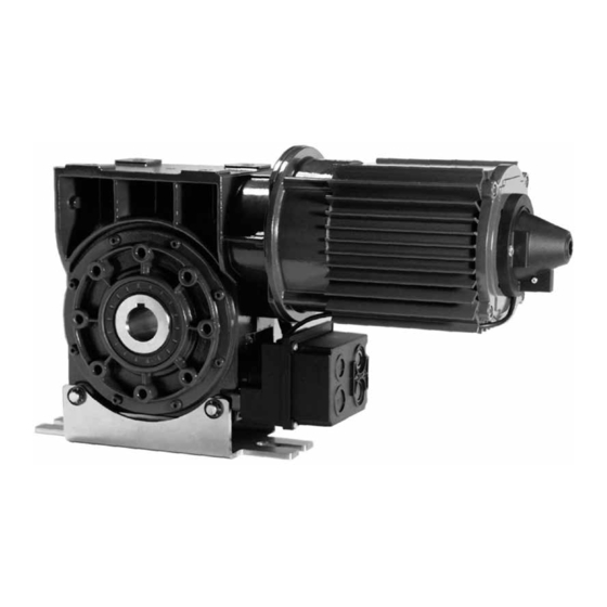
Gearmotors for rolling shutters
IT -
Istruzioni e indicazioni d'installazione e uso
L'intero manuale d'istruzioni è composto delle istruzioni per l'uso rispettivamente del motoriduttore e della relativa centrale di comando.
EN -
Instructions and information for installation and use
The entire instruction manual is made up of instructions for use regarding the gearmotor and its control unit.
FR -
Instructions et indications d'installation et d'utilisation
L'ensemble du manuel d'instructions comprend les instructions pour utiliser respectivement le motoréducteur et sa centrale de commande.
ES -
Instrucciones e indicaciones para la instalación y el uso
El manual de instrucciones está compuesto por las instrucciones de uso del motorreductor y de la central de mando relativa.
DE -
Anweisungen und Hinweise für Installation und Bedienung
Die Gesamt-Bedienungsanleitung besteht aus der BA des Antriebes und der dazugehörigen BA der Steuerung.
PL -
Instrukcja i wskazówki na temat instalacji i eksploatacji
Cała instrukcja obsługi zawiera instrukcje dotyczące obsługi odpowiednio motoreduktora oraz właściwej centrali sterowniczej.
NL -
Instructies en aanwijzingen voor de installatie en het gebruik
De volledige instructiehandleiding bestaat uit de gebruiksaanwijzingen voor het gebruik van respectievelijk de reductiemotor en
van de bijbehorende bedieningscentrale
Advertisement
Chapters
Table of Contents

Related Manuals for Nice RDF Series


Summary of Contents for Nice RDF Series
- Page 1 Gearmotors for rolling shutters IT - Istruzioni e indicazioni d’installazione e uso L‘intero manuale d‘istruzioni è composto delle istruzioni per l‘uso rispettivamente del motoriduttore e della relativa centrale di comando. EN - Instructions and information for installation and use The entire instruction manual is made up of instructions for use regarding the gearmotor and its control unit. FR - Instructions et indications d’installation et d’utilisation L’ensemble du manuel d’instructions comprend les instructions pour utiliser respectivement le motoréducteur et sa centrale de commande.
-
Page 2: Table Of Contents
TABLE OF CONTENTS GENERAL INFORMATION.........................3 SAFETY STANDARDS........................3 INSTALLATION RULES........................3 GENERAL DANGER WARNINGS AND PREVENTIVE SAFETY............4 PARACHUTE DEVICE BUILT INTO THE REDUCTION UNIT............4 REDUCTION UNIT PARACHUTE DEVICE ..................4 EMERGENCY MANUAL RELEASES....................4 LIMIT SWITCH SETTING........................5 STAR-DELTA VOLTAGE CONNECTION....................5 ANNUAL CHECK..........................6 TECHNICAL SPECIFICATIONS......................6 FIGURES.............................7 CONNECTION CABLE FOR CONTROLS EQUIPPED WITH MECHANICAL LIMIT SWITCH WITH SCREENING...........................10... -
Page 3: General Information
Failure to observe the above can damage the product, and increase the risk of danger or malfunction. Should this occur, sus pend installation work immediately and contact the Nice Support Service. • The electrical power line must be fitted with a device that ena... -
Page 4: General Danger Warnings And Preventive Safety
GENERAL DANGER WARNINGS AND PARACHUTE DEVICE PREVENTIVE SAFETY BUILT INTO THE REDUCTION UNIT According to the VDE 0113 booklet, the emergency stop The gearmotors are positive clutch startup controls with builtin devices must also be perfectly efficient regardless of the parachute device, irrespective of the rpm and position. -
Page 5: Limit Switch Setting
Chain version (fig. 5a-d) The safety limit switches 2 SE and 4 SEh (red) must be set in order to be released right after the overtaking of the control limit switch. Grasp the red handle / manual control (1) and softly pull until stopping The safety limit switches 2 SE... -
Page 6: Annual Check
TECHNICAL SPECIFICATIONS NOTE: all the technical characteristics indicated refer to a temperature falling beetwen 5°C and +40°C. • Nice reserves the right to change all the modifications to the product it deems necessary at any time, but keeping the functions and intended use unaltered. - Page 7 Shaft assembly Assembly of bracket for large gearmotors Central winding shaft Screw tightening torque = 20 Nm Assembly of bracket for small gearmotors Motor Motor Wand Wall Grün Green English – 7...
- Page 8 Emergency release chain Mechanical limit switches Small types Large types Mechanical limit switch setting Mechanical limit switch setting Large types - 7 Contactor cam Small itypes - 8 Contactor cam 8 white Additional limit switch 2 CLOSE 7 white Additional limit switch 2 CLOSE Optional Optional 7 green Additional limit switch 2 OPEN...
- Page 9 Motor connection with Delta connection terminal block yellow brown black green blue Standard wiring 3~400V 3~400V blue blue blue yellow blue yellow green green black green black green brown brown black brown brown black Centrale Reductiemotor Motor X2 J1/U UST1/U X2 ...
-
Page 10: With Screening
CONNECTION CABLE FOR CONTROLS EQUIPPED WITH MECHANICAL LIMIT SWITCH WITH SCREENING 10 – English... - Page 11 CONNECTION CABLE FOR CONTROLS EQUIPPED WITH ELECTRONIC LIMIT SWITCH WITHOUT SCREENING English – 11...
- Page 12 CONNECTION CABLE FOR CONTROLS EQUIPPED WITH ELECTRONIC LIMIT SWITCH WITH SCREENING 12 – English...
-
Page 13: Dimensioned Gearmotor Drawings For Rolling Shutters
DIMENSIONED GEARMOTOR DRAWINGS FOR ROLLING SHUTTERS Gearmotors with handle and chain RDF-140-20-KU RDF-140-20-KE2 Ø 10mm English – 13... - Page 14 DIMENSIONED DRAWINGS OF GEARMOTORS FOR ROLLING SHUTTERS Gearmotors with handle and chain RDF-220/290-15-KU RDF-220/290-15-KE2 Ø 12mm table table elektronische electronic limit Endschalter switches mechanische mechanical limit Endschalter switches 14 – English...
- Page 15 DIMENSIONED DRAWINGS OF GEARMOTORS FOR ROLLING SHUTTERS Gearmotors with handle and chain RDF-380/450-15-KU RDF-380/450-15-KE2 Ø 12mm English – 15...
- Page 16 DIMENSIONED DRAWINGS OF GEARMOTORS FOR ROLLING SHUTTERS Gearmotors with handle and chain RDF-550-12-KU RDF-550-12-KE2 Ø 12mm 16 – English...
- Page 17 DIMENSIONED DRAWINGS OF GEARMOTORS FOR ROLLING SHUTTERS Gearmotors with handle and chain RDF-750-9,5-KU RDF-750-9,5-KE2 Ø 15mm English – 17...
- Page 18 DIMENSIONED GEARMOTOR DRAWINGS FOR ROLLING SHUTTERS Gearmotors with handle and chain RDF-850/1100-10-KU RDF-850/1100-10-KE2 Ø 15mm 18 – English...
- Page 19 DIMENSIONED GEARMOTOR DRAWINGS FOR ROLLING SHUTTERS Gearmotors with handle and chain RDF-1400-7-KU RDF-1400-7-KE2 Ø 15mm English – 19...
- Page 20 DIMENSIONED GEARMOTOR DRAWINGSFOR ROLLING SHUTTERS Gearmotors with handle and chain RDF-250-24-KU RDF-250-24-KE2 Ø 12mm 20 – English...
- Page 21 DIMENSIONED GEARMOTOR DRAWINGS FOR ROLLING SHUTTERS Gearmotors with handle and chain RDF-350-24-KU RDF-350-24-KE2 Ø 12mm English – 21...
- Page 22 DIMENSIONED GEARMOTOR DRAWINGS FOR ROLLING SHUTTERS Gearmotors with handle and chain RDF-500-24-KU RDF-500-24-KE2 Ø 12mm 22 – English...
- Page 23 DIMENSIONED GEARMOTOR DRAWINGS FOR ROLLING SHUTTERS Gearmotors with handle and chain RDF-750-24-KU RDF-750-24-KE2 Ø 15mm English – 23...
- Page 24 DIMENSIONED GEARMOTOR DRAWINGS FOR ROLLING SHUTTERS Gearmotors with handle and chain RDF-950-24-KU RDF-950-24-KE2 Ø 15mm 24 – English...
- Page 25 DIMENSIONED GEARMOTOR DRAWINGS FOR ROLLING SHUTTERS Gearmotors with handle and chain RDF-1250-24-KU RDF-1250-24-KE2 Ø 15mm English – 25...
- Page 26 DIMENSIONED GEARMOTOR DRAWINGS FOR ROLLING SHUTTERS Gearmotors with handle and chain RDF-1400-24-KU RDF-1400-24-KE2 Ø 15mm 26 – English...
-
Page 27: Combination Of Gearmotors For Rolling Shutters And Control Stations
For disposal, it is necessary to separate NICE declines all liability and disclaims any warranty whatsoever − metals for damages, if any, caused by nonoriginal spare parts and/or −... - Page 28 INDICE INDICAZIONI GENERALI........................3 NORME DI SICUREZZA........................3 NORME DI INSTALLAZIONE......................3 PERICOLI GENERICI E NORME DI SICUREZZA................4 ISTRUZIONI DI MONTAGGIO / FISSAGGIO DEL MECCANISMO..........4 DISPOSITIVO PARACADUTE NEL RIDUTTORE................4 SBLOCCO MANUALE D’EMERGENZA..................4 IMPOSTAZIONE FINECORSA......................5 COLLEGAMENTO TENSIONE STELLA - TRIANGOLO..............5 CONTROLLO ANNUALE........................6 DATI TECNICI.............................6 FIGURE..........................7 FIGURE..........................8 FIGURE..........................9...
-
Page 29: Indicazioni Generali
Tutte queste azioni possono danneggiarlo ed esse- re causa di malfunzionamenti o situazioni di pericolo. Se questo accade, sospendere immediatamente l’installazione e rivolgersi al Servizio Assistenza Nice. • Sulla linea elettrica di alimentazione, è necessario prevedere un dispositivo che assicuri la disconnessione completa dell’automa- zione dalla rete. -
Page 30: Istruzioni Di Montaggio / Fissaggio Del Meccanismo
AVVERTENZE DI PERICOLO GENERICHE DISPOSITIVO PARACADUTE INCORPORATO E SICUREZZA PREVENTIVA NEL RIDUTTORE I dispositivi di arresto d’emergenza secondo il fascicolo I motoriduttori sono comandi di avviamento a innesto con dispositivo VDE 0113 devono mantenersi sempre in perfetta efficienza paracadute incorporato, indipendente dal numero dei giri e dalla indipendentemente dalla modalità... -
Page 31: Impostazione Finecorsa
comando, e impedire quindi l’azionamento della porta in modalità I finecorsa di sicurezza 2 SE e 4 SEh (rossi) vanno impostati in elettrica. modo che scattino subito dopo il superamento del finecorsa di comando. - Aprire e/o chiudere la porta con la catena di sblocco d’emergenza (2) - Afferrare l’impugnatura verde / comando motore (3) e tirare delicatamente I finecorsa di sicurezza 2 SE... -
Page 32: Controllo Annuale
DATI TECNICI NOTA BENE: tutte le caratteristiche tecniche indicate si riferiscono ad una temperatura compresa tra -5°C e +40°C. • La Nice si riserva il diritto di apportare in qualunque momento tutte le modifiche al prodotto che ritiene necessarie, mantenendo comunque inalterate la funzionalità... - Page 33 Montaggio albero Montaggio staffa per motoriduttori di grosse dimensioni Albero di avvolgimento centrale Coppia di serraggio delle viti = 20 Nm Montaggio staffa per motoriduttori di piccole dimensioni Motor Motore Wand Parete Rosso Grün Verde Italiano – 7...
- Page 34 Catena di sblocco d’emergenza Finecorsa meccanici Tipi di piccole dimensioni Tipi di grosse dimensioni Impostazione finecorsa meccanico Impostazione finecorsa meccanico Tipi di grosse dimensioni - 7 Camma Tipi di piccole dimensioni - 8 Camma di contattore di contattore 8 bianco Finecorsa supplementare 2 CHIUSURA 7 bianco Finecorsa supplementare 2 CHIUSURA...
- Page 35 Connessione motore con morsettiera Collegamento a triangolo giallo marrone nero verde rosso azzurro 3~400V 3~230V Cablaggio standard blue bleu azzurro bleu azzurro blue yellow giallo yellow giallo blue yellow black nero black nero green verde green verde brown marrone brown marrone green rosso...
- Page 36 CAVO DI COLLEGAMENTO PER COMANDI DOTATI DI INTERRUTTORE DI FINECORSA MECCANICO CON SCHERMATURA 10 – Italiano...
- Page 37 CAVO DI COLLEGAMENTO PER COMANDI DOTATI DI INTERRUTTORE DI FINECORSA ELETTRONICO SENZA SCHERMATURA Italiano – 11...
- Page 38 CAVO DI COLLEGAMENTO PER COMANDI DOTATI DI INTERRUTTORE DI FINECORSA ELETTRONICO CON SCHERMATURA 12 – Italiano...
-
Page 39: Disegni Quotati Motoriduttori
DISEGNI QUOTATI MOTORIDUTTORI PER SERRANDE AVVOLGIBILI Motoriduttori con manovella e catena RDF-140-20-KU RDF-140-20-KE2 Ø 10mm Italiano – 13... - Page 40 DISEGNI QUOTATI MOTORIDUTTORI PER SERRANDE AVVOLGIBILI Motoriduttori con manovella e catena RDF-220/290-15-KU RDF-220/290-15-KE2 Ø 12mm table tabella elektronische finecorsa elettronici Endschalter mechanische finecorsa meccanici Endschalter 14 – Italiano...
- Page 41 DISEGNI QUOTATI MOTORIDUTTORI PER SERRANDE AVVOLGIBILI Motoriduttori con manovella e catena RDF-380/450-15-KU RDF-380/450-15-KE2 Ø 12mm Italiano – 15...
- Page 42 DISEGNI QUOTATI MOTORIDUTTORI PER SERRANDE AVVOLGIBILI Motoriduttori con manovella e catena RDF-550-12-KU RDF-550-12-KE2 Ø 12mm 16 – Italiano...
- Page 43 DISEGNI QUOTATI MOTORIDUTTORI PER SERRANDE AVVOLGIBILI Motoriduttori con manovella e catena RDF-750-9,5-KU RDF-750-9,5-KE2 Ø 15mm Italiano – 17...
- Page 44 DISEGNI QUOTATI MOTORIDUTTORI PER SERRANDE AVVOLGIBILI Motoriduttori con manovella e catena RDF-850/1100-10-KU RDF-850/1100-10-KE2 Ø 15mm 18 – Italiano...
- Page 45 DISEGNI QUOTATI MOTORIDUTTORI PER SERRANDE AVVOLGIBILI Motoriduttori con manovella e catena RDF-1400-7-KU RDF-1400-7-KE2 Ø 15mm Italiano – 19...
- Page 46 DISEGNI QUOTATI MOTORIDUTTORI PER SERRANDE AVVOLGIBILI Motoriduttori con manovella e catena RDF-250-24-KU RDF-250-24-KE2 Ø 12mm 20 – Italiano...
- Page 47 DISEGNI QUOTATI MOTORIDUTTORIPER SERRANDE AVVOLGIBILI Motoriduttori con manovella e catena RDF-350-24-KU RDF-350-24-KE2 Ø 12mm Italiano – 21...
- Page 48 DISEGNI QUOTATI MOTORIDUTTORI PER SERRANDE AVVOLGIBILI Motoriduttori con manovella e catena RDF-500-24-KU RDF-500-24-KE2 Ø 12mm 22 – Italiano...
- Page 49 DISEGNI QUOTATI MOTORIDUTTORI PER SERRANDE AVVOLGIBILI Motoriduttori con manovella e catena RDF-750-24-KU RDF-750-24-KE2 Ø 15mm Italiano – 23...
- Page 50 DISEGNI QUOTATI MOTORIDUTTORI PER SERRANDE AVVOLGIBILI Motoriduttori con manovella e catena RDF-950-24-KU RDF-950-24-KE2 Ø 15mm 24 – Italiano...
- Page 51 DISEGNI QUOTATI MOTORIDUTTORI PER SERRANDE AVVOLGIBILI Motoriduttori con manovella e catena RDF-1250-24-KU RDF-1250-24-KE2 Ø 15mm Italiano – 25...
- Page 52 DISEGNI QUOTATI MOTORIDUTTORI PER SERRANDE AVVOLGIBILI Motoriduttori con manovella e catena RDF-1400-24-KU RDF-1400-24-KE2 Ø 15mm 26 – Italiano...
-
Page 53: Trasporto / Magazzinaggio/ Smaltimento
Per lo smaltimento occorre separare progettazione costruttiva, ovvero ripercuotersi sulla sicurezza. − metalli La NICE declina ogni responsabilità e nega qualsivoglia garanzia per − elementi in plastica gli eventuali danni provocati attraverso l’uso di parti di ricambio e/o − componenti elettrici accessori non originali. - Page 54 SOMMAIRE INDICATIONS GÉNÉRALES......................3 NORMES DE SÉCURITÉ........................3 NORMES D'INSTALLATION......................3 DANGERS GÉNÉRIQUES ET CONSIGNES DE SÉCURITÉ............4 INSTRUCTIONS DE MONTAGE / FIXATION DU MÉCANISME..........4 DISPOSITIF PARACHUTES DANS LE RÉDUCTEUR..............4 DÉBLOCAGE MANUEL D'URGENCE....................4 RÉGLAGE FIN DE COURSE......................5 RACCORDEMENT DE TENSION ÉTOILE-TRIANGLE..............5 CONTRÔLE ANNUEL........................6 CARACTÉRISTIQUES TECHNIQUES....................6 FIGURES..........................7 FIGURES..........................8 FIGURES..........................9...
-
Page 55: Indications Générales
• description générale du produit le cas échéant, si la complexité de manuel. En cas de doutes, interrompre l’installation et demander celui-ci l’impose ; des précisions au service après-vente Nice. • précautions spécifiques nécessaires pendant l’installation, l’utilisa- • ATTENTION ! – Instructions importantes : conserver ce tion, le réglage, la maintenance, le nettoyage, la réparation ou le... -
Page 56: Instructions De Montage / Fixation Du Mécanisme
AVERTISSEMENTS GÉNÉRIQUES DE DANGER DISPOSITIF PARACHUTES INTÉGRÉ ET SÉCURITÉ PRÉVENTIVE DANS LE RÉDUCTEUR Conformément à la norme VDE 0113, les dispositifs d'arrêt Les motoréducteurs sont des commandes de démarrage à d'urgence doivent toujours être conservés en parfait état de enclenchement avec dispositif parachutes intégré, indépendant du fonctionnement quel que soit le mode de fonctionnement du nombre de tours et de la position. -
Page 57: Réglage Fin De Course
- Ouvrir et/ou fermer la porte avec la chaîne de déblocage d’urgence (2) Pour le réglage de précision, agir sur la vis B. - Saisir la poignée verte / la commande moteur (3) et tirer délicatement Les fins de course de sécurité 2 SE et 4 SEh (rouges) sont réglés de jusqu’à... -
Page 58: Contrôle Annuel
Avant de procéder au remplacement, débrancher les câbles reliés à la fiche électrique. CARACTÉRISTIQUES TECHNIQUES NOTE : toutes les caractéristiques techniques indiquées se réfèrent à une température comprise entre -5 °C et +40 °C. • La société Nice se réserve le droit d'apporter à tout moment au produit toutes les modifications qu'elle jugerait nécessaires tout en laissant inchangées les fonctions et l'utilisation prévue. - Page 59 Montage de l'arbre Montage de l'étrier pour motoréducteurs de grandes dimensions Arbre central d'enroulement Couple de serrage des vis = 20 Nm Montage de l'étrier pour motoréducteurs de petites dimensions Motor Moteur Wand Rouge Grün Vert Français – 7...
- Page 60 Chaîne de déblocage d'urgence Fins de course mécaniques Types de dimensions réduites Types de grandes dimensions Réglage du fin de course mécanique Réglage du fin de course mécanique Types de grandes dimensions - 7 Types de dimensions réduites - 8 Came de contacteur Came de contacteur 8 blanc Fin de course supplémentaire 2 FERMETURE...
- Page 61 Connexion du moteur avec Raccordement en triangle bornier jaune marron noir vert rouge bleu 3~400V 3~400V Câblage standard blue bleu bleu bleu bleu blue yellow jaune yellow jaune blue yellow black noir black noir green vert green vert brown marron brown marron green...
- Page 62 CÂBLE DE CONNEXION POUR LES COMMANDES MUNIES D'INTERRUPTEUR DE FIN DE COURSE MÉCANIQUE AVEC BLINDAGE 10 – Français...
- Page 63 CÂBLE DE CONNEXION POUR LES COMMANDES MUNIES D'INTERRUPTEUR DE FIN DE COURSE ÉLECTRONIQUE SANS BLINDAGE Français – 11...
- Page 64 CÂBLE DE CONNEXION POUR LES COMMANDES MUNIES D'INTERRUPTEUR DE FIN DE COURSE ÉLECTRONIQUE AVEC BLINDAGE 12 – Français...
-
Page 65: Schémas Côtés Motoréducteurs
SCHÉMAS CÔTÉS MOTORÉDUCTEURS POUR VOLETS ROULANTS Motoréducteurs avec manivelle et chaîne RDF-140-20-KU RDF-140-20-KE2 Ø 10 mm Français – 13... - Page 66 SCHÉMAS CÔTÉS MOTORÉDUCTEURS POUR VOLETS ROULANTS Motoréducteurs avec manivelle et chaîne RDF-220/290-15-KU RDF-220/290-15-KE2 Ø 12 mm table tableau elektronische fins de course Endschalter électroniques mechanische fins de course Endschalter mécaniques 14 – Français...
- Page 67 SCHÉMAS CÔTÉS MOTORÉDUCTEURS POUR VOLETS ROULANTS Motoréducteurs avec manivelle et chaîne RDF-380/450-15-KU RDF-380/450-15-KE2 Ø 12 mm Français – 15...
- Page 68 SCHÉMAS CÔTÉS MOTORÉDUCTEURS POUR VOLETS ROULANTS Motoréducteurs avec manivelle et chaîne RDF-550-12-KU RDF-550-12-KE2 Ø 12 mm 16 – Français...
- Page 69 SCHÉMAS CÔTÉS MOTORÉDUCTEURS POUR VOLETS ROULANTS Motoréducteurs avec manivelle et chaîne RDF-750-9,5-KU RDF-750-9,5-KE2 Ø 15 mm Français – 17...
- Page 70 SCHÉMAS CÔTÉS MOTORÉDUCTEURS POUR VOLETS ROULANTS Motoréducteurs avec manivelle et chaîne RDF-850/1100-10-KU RDF-850/1100-10-KE2 Ø 15 mm 18 – Français...
- Page 71 SCHÉMAS CÔTÉS MOTORÉDUCTEURS POUR VOLETS ROULANTS Motoréducteurs avec manivelle et chaîne RDF-1400-7-KU RDF-1400-7-KE2 Ø 15 mm Français – 19...
- Page 72 SCHÉMAS CÔTÉS MOTORÉDUCTEURS POUR VOLETS ROULANTS Motoréducteurs avec manivelle et chaîne RDF-250-24-KU RDF-250-24-KE2 Ø 12 mm 20 – Français...
- Page 73 SCHÉMAS CÔTÉS MOTORÉDUCTEURS POUR VOLETS ROULANTS Motoréducteurs avec manivelle et chaîne RDF-350-24-KU RDF-350-24-KE2 Ø 12 mm Français – 21...
- Page 74 SCHÉMAS CÔTÉS MOTORÉDUCTEURS POUR VOLETS ROULANTS Motoréducteurs avec manivelle et chaîne RDF-500-24-KU RDF-500-24-KE2 Ø 12 mm 22 – Français...
- Page 75 SCHÉMAS CÔTÉS MOTORÉDUCTEURS POUR VOLETS ROULANTS Motoréducteurs avec manivelle et chaîne RDF-750-24-KU RDF-750-24-KE2 Ø 15 mm Français – 23...
- Page 76 SCHÉMAS CÔTÉS MOTORÉDUCTEURS POUR VOLETS ROULANTS Motoréducteurs avec manivelle et chaîne RDF-950-24-KU RDF-950-24-KE2 Ø 15 mm 24 – Français...
- Page 77 SCHÉMAS CÔTÉS MOTORÉDUCTEURS POUR VOLETS ROULANTS Motoréducteurs avec manivelle et chaîne RDF-1250-24-KU RDF-1250-24-KE2 Ø 15 mm Français – 25...
- Page 78 SCHÉMAS CÔTÉS MOTORÉDUCTEURS POUR VOLETS ROULANTS Motoréducteurs avec manivelle et chaîne RDF-1400-24-KU RDF-1400-24-KE2 Ø 15 mm 26 – Français...
-
Page 79: Transport / Stockage / Élimination
− les métaux la sécurité. − les éléments en plastique La société NICE décline toute responsabilité et refuse toute garantie − les composants électriques pour les dommages éventuellement provoqués par l'utilisation de − les lubrifiants. pièces détachées et/ou d'accessoires qui ne sont pas d'origine. - Page 80 ÍNDICE INDICACIONES GENERALES......................3 NORMAS DE SEGURIDAD.......................3 NORMAS DE INSTALACIÓN......................3 PELIGROS GENÉRICOS Y NORMAS DE SEGURIDAD...............4 INSTRUCCIONES DE MONTAJE / FIJACIÓN DEL MECANISMO..........4 DISPOSITIVO PARACAÍDAS EN EL REDUCTOR................4 DESBLOQUEO MANUAL DE EMERGENCIA.................4 AJUSTE DEL INTERRUPTOR DE TOPE..................5 CONEXIÓN DE TENSIÓN ESTRELLA-DELTA................5 CONTROL ANUAL..........................6 DATOS TÉCNICOS...........................6 FIGURAS..........................7...
-
Page 81: Indicaciones Generales
Todas estas acciones pueden dañarlo y provocar funcionamientos defectuosos o situaciones de peligro. Si ocurriese esto, interrumpa inmediatamente la instalación y acu- da al Servicio de Asistencia Nice. • En la línea eléctrica de alimentación es necesario montar un dis- positivo que asegure la desconexión completa del automatismo de la red. -
Page 82: Instrucciones De Montaje / Fijación Del Mecanismo
ADVERTENCIAS DE PELIGRO GENÉRICAS DISPOSITIVO PARACAÍDAS Y SEGURIDAD PREVENTIVA INCORPORADO EN EL MOTORREDUCTOR Los dispositivos de parada de emergencia según el fascículo Los motorreductores son accionamientos de arranque con mando, VDE 0113 deben mantenerse siempre en perfecta eficiencia, con dispositivo paracaídas incorporado, independiente del número independientemente del modo de funcionamiento del de revoluciones y de la posición. -
Page 83: Ajuste Del Interruptor De Tope
Versión de cadena (figg. 5a-d) Para un ajuste de precisión, ajustar el tornillo B. - Tomar la empuñadura roja / el mando manual (1) y tirar delicadamente Los interruptores de tope de seguridad 2 SE y 4 SEh (rojos) se hasta la parada para interrumpir la tensión de mando e impedir con deben ajustar en modo tal que se disparen inmediatamente cuando ello el accionamiento de la puerta en modo eléctrico. -
Page 84: Control Anual
Durante el control anual se debe verificar el funcionamiento impecable del freno. En caso de fuerte desgaste de las pastillas de freno, es necesario cambiar todo el freno. Antes de proceder a la sustitución, desconectar los cables conectados a la tarjeta eléctrica. DATOS TÉCNICOS NOTA: todas las características técnicas indicadas se refieren a una temperatura comprendida entre -5 °C y 40 °C. • NICE se reserva el derecho de realizar, en cualquier momento, todas las modificaciones al producto que considere necesarias, sin modificar las funciones ni el uso previsto. Datos técnicos Modelo RDF-... - Page 85 Montaje del eje Montaje del soporte para motorreductores de grandes dimensiones Eje de enrollado central Par de apriete de los tornillos = 20Nm Montaje del soporte para motorreductores de pequeñas dimensiones Motor Motor Wand Pared Rojo Grün Verde Español – 7...
- Page 86 Cadena de desbloqueo de emergencia Interruptores de tope mecánicos Tipos de pequeñas dimensiones Tipos de grandes dimensiones Ajuste del interruptor de tope mecánico Ajuste del interruptor de tope mecánico Tipos de grandes dimensiones - 7 Tipos de pequeñas dimensiones - 8 Leva del contactor Leva del contactor 8 blanco Interruptor de tope suplementario 2 CIERRE...
- Page 87 Conexión en delta Acoplamiento motor CIMA amarillo marrón negro verde rojo azul 3~400V Cableado estándar 3~400V blue bleu azul bleu azul blue yellow amarillo yellow amarillo blue yellow black negro black negro green verde green verde brown marrón brown marrón green rojo rojo...
- Page 88 CABLE DE CONEXIÓN PARA MANDOS EQUIPADOS CON INTERRUPTOR DE TOPE MECÁNICO CON APANTALLADO 10 – Español...
- Page 89 CABLE DE CONEXIÓN PARA MANDOS EQUIPADO CON INTERRUPTOR DE TOPE ELECTRÓNICO SIN APANTALLADO Español – 11...
- Page 90 CABLE DE CONEXIÓN PARA MANDOS EQUIPADOS CON INTERRUPTOR DE TOPE ELECTRÓNICO CON APANTALLADO 12 – Español...
-
Page 91: Esquemas Acotados Del Motorreductor
ESQUEMAS ACOTADOS DEL MOTORREDUCTOR PARA PERSIANAS METÁLICAS Motorreductores con manivela de cadena RDF-140-20-KU RDF-140-20-KE2 Ø 10mm Español – 13... - Page 92 ESQUEMAS ACOTADOS DE LOS MOTORREDUCTORES PARA PERSIANAS METÁLICAS Motorreductores con manivela de cadena RDF-220/290-15-KU RDF-220/290-15-KE2 Ø 12mm table tabla elektronische interruptores de tope Endschalter electrónicos mechanische interruptores de tope Endschalter mecánicos 14 – Español...
- Page 93 ESQUEMAS ACOTADOS DE LOS MOTORREDUCTORES PARA PERSIANAS METÁLICAS Motorreductores con manivela de cadena RDF-380/450-15-KU RDF-380/450-15-KE2 Ø 12mm Español – 15...
- Page 94 ESQUEMAS ACOTADOS DE LOS MOTORREDUCTORES PARA PERSIANAS METÁLICAS Motorreductores con manivela de cadena RDF-550-12-KU RDF-550-12-KE2 Ø 12mm 16 – Español...
- Page 95 ESQUEMAS ACOTADOS DEL MOTORREDUCTOR PARA PERSIANAS METÁLICAS Motorreductores con manivela de cadena RDF-750-9,5-KU RDF-750-9,5-KE2 Ø 15mm Español – 17...
- Page 96 ESQUEMAS ACOTADOS DEL MOTORREDUCTOR PARA PERSIANAS METÁLICAS Motorreductores con manivela de cadena RDF-850/1100-10-KU RDF-850/1100-10-KE2 Ø 15mm 18 – Español...
- Page 97 ESQUEMAS ACOTADOS DEL MOTORREDUCTOR PARA PERSIANAS METÁLICAS Motorreductores con manivela de cadena RDF-1400-7-KU RDF-1400-7-KE2 Ø 15mm Español – 19...
- Page 98 ESQUEMAS ACOTADOS DEL MOTORREDUCTOR PARA PERSIANAS METÁLICAS Motorreductores con manivela de cadena RDF-250-24-KU RDF-250-24-KE2 Ø 12mm 20 – Español...
- Page 99 ESQUEMAS ACOTADOS DEL MOTORREDUCTOR PARA PERSIANAS METÁLICAS Motorreductores con manivela de cadena RDF-350-24-KU RDF-350-24-KE2 Ø 12mm Español – 21...
- Page 100 ESQUEMAS ACOTADOS DEL MOTORREDUCTOR PARA PERSIANAS METÁLICAS Motorreductores con manivela de cadena RDF-500-24-KU RDF-500-24-KE2 Ø 12mm 22 – Español...
- Page 101 ESQUEMAS ACOTADOS DEL MOTORREDUCTOR PARA PERSIANAS METÁLICAS Motorreductores con manivela de cadena RDF-750-24-KU RDF-750-24-KE2 Ø 15mm Español – 23...
- Page 102 ESQUEMAS ACOTADOS DEL MOTORREDUCTOR PARA PERSIANAS METÁLICAS Motorreductores con manivela de cadena RDF-950-24-KU RDF-950-24-KE2 Ø 15mm 24 – Español...
- Page 103 ESQUEMAS ACOTADOS DEL MOTORREDUCTOR PARA PERSIANAS METÁLICAS Motorreductores con manivela de cadena RDF-1250-24-KU RDF-1250-24-KE2 Ø 15mm Español – 25...
- Page 104 ESQUEMAS ACOTADOS DEL MOTORREDUCTOR PARA PERSIANAS METÁLICAS Motorreductores con manivela de cadena RDF-1400-24-KU RDF-1400-24-KE2 Ø 15mm 26 – Español...
-
Page 105: Transporte / Almacenamiento / Eliminación
Por lo tanto, el montaje y/o la utilización de productos de este tipo de características análogas. pudieran modificar eventuales características predefinidas a nivel de Para su eliminación hay que separar diseño constructivo, con repercusiones en la seguridad. − metales NICE declina cualquier responsabilidad y niega cualquier tipo de − elementos de plástico garantía por los eventuales daños provocados por el uso de piezas − componentes eléctricos de repuesto y/o accesorios no originales. − lubrificantes... - Page 106 INHALTSVERZEICHNIS ALLGEMEINE HINWEISE........................3 SICHERHEITSHINWEISE........................3 SICHERHEITSRELEVANTE VORSCHRIFTEN..................3 ALLGEMEINE GEFAHRENHINWEISE UND SICHERHEITSVORSCHRIFTEN........4 MONTAGEHINWEISE/GETRIEBEBEFESTIGUNG................4 FANGVORRICHTUNG IM GETRIEBE ....................4 NOTHANDBETÄTIGUNG........................4 ENDSCHALTEREINSTELLUNG......................5 SPANNUNGSUMSCHALTUNG STERN - DREIECK ................5 JÄHRLICHE PRÜFUNG........................6 TECHNISCHE DATEN........................6 ABBILDUNGEN..........................7 ABBILDUNGEN..........................8 ABBILDUNGEN..........................9 ANSCHLUSSKABEL ANTRIEBE....................10-12 MASSZEICHNUNGEN ANTRIEBE.....................13-27 TRANSPORT / LAGERUNG / ENTSORGUNG................28 SERVICE / ERSATZTEILE / ZUBEHÖR..................29 KONFORMITÄTSERKLÄRUNG (Herstellererklärung)..............29 2 –...
-
Page 107: Allgemeine Hinweise
Wärmequelle oder einer offenen Flamme aussetzen. All dies kann zu Beschädigungen führen und Betriebsstörungen oder gefährliche Situationen hervorrufen. Sollte dies der Fall sein, die Installation sofort abbrechen und den Kundendienst Nice verstän- digen. • An der Netzstromleitung muss eine Vorrichtung vorgesehen werden, die die vollständige Trennung der Automatisierung... -
Page 108: Allgemeine Gefahrenhinweise Und Sicherheitsvorschriften
ALLGEMEINE GEFAHRENHINWEISE UND FANGVORRICHTUNG IM GETRIEBE SICHERHEITSVORKEHRUNGEN NOT-AUS-Einrichtungen gemäß VDE 0113 müssen in allen Die Antriebe sind Aufsteckantriebe mit einer eingebauten, drehzahl- Betriebsarten der Steuerung wirksam bleiben. Eine Entriegelung und lageunabhängigen Fangvorrichtung. der NOT-AUS Einrichtung darf keinen unkontrollierten oder Die Fangvorrichtung läuft belastungs- und verschleißfrei mit und undefinierten Wiederanlauf bewirken. -
Page 109: Endschaltereinstellung
Ausführung: „Kette“ (Abb. 5a-d) Die Feineinstellung wird mit der Schraube B vorgenommen. - roten Griff / Handbetrieb (1) leicht bis zum Die Sicherheitsendschalter 2 SEi und 4 SEh (rot) müssen so Anschlag ziehen, die Steuerspannung ist hierdurch unterbrochen eingestellt werden, dass sie sofort nach dem Überfahren der und das Tor kann elektrisch nicht mehr betrieben werden. -
Page 110: Jährliche Prüfung
Gleichrichters die komplette Bremse getauscht werden. TECHNISCHE DATEN HINWEISE : Alle angegebenen technischen Merkmale beziehen sich auf eine Temperatur von -5°C bis +40°C. • Nice behält sich das Recht vor, jederzeit als nötig betrachtete Änderungen am Produkt vorzunehmen, wobei die Funktionalitäten und der Einsatzzweck beibe- halten werden. - Page 111 Montage Antrieb-Welle Montage Antrieb-Pendelfuß - große Getriebe Mitte Wickelwelle Anzugsmoment der Schrauben = 20 Nm Montage Antrieb-Pendelfuß kleines Getriebe Deutsch – 7...
- Page 112 Haspelkette Mechan. Endschalter kleine Typen große Typen Einstellung mechan. Endschalter Einstellung mechan. Endschalter große Antriebstypen - 7 Schaltnocken kleine Antriebstypen - 8 Schaltnocken 8 weiß Zusatzendschalter 2 ZU 7 weiß Zusatzendschalter 2 ZU Optional Optional 7 grün Zusatzendschalter 2 AUF 6 grün Zusatzendschalter 2 AUF 6 weiß...
- Page 113 Anschluss Motor mit Dreieck Schaltung Klemmenleiste gelb braun schwarz grün blau 3~230V 3~400V Standard-Verdrahtung blau blau blau gelb blau grün grün grün schwarz grün braun schwarz braun braun schwarz Steuer u ng A der M oto r X2 - J1 / U AMP-Stecker X2 - J1 / V X2 - J1 / W...
- Page 114 ANSCHLUSSKABEL FÜR ANTRIEBE MIT MECH. ENDSCHALTER - ABGESCHIRMT 10 – Deutsch...
- Page 115 ANSCHLUSSKABEL FÜR ANTRIEBE MIT ELEKTRON. ENDSCHALTER - NICHT ABGESCHIRMT Deutsch – 11...
- Page 116 ANSCHLUSSKABEL FÜR ANTRIEBE MIT ELEKTRON. ENDSCHALTER - ABGESCHIRMT 12 – Deutsch...
- Page 117 MASSZEICHNUNGEN ROLLTORANTRIEBE Antriebe mit Kurbel und Kette RDF-140-20-KU RDF-140-20-KE2 Ø 10mm Deutsch – 13...
- Page 118 MASSZEICHNUNGEN ROLLTORANTRIEBE Antriebe mit Kurbel und Kette RDF-220/290-15-KU RDF-220/290-15-KE2 Ø 12mm 14 – Deutsch...
- Page 119 MASSZEICHNUNGEN ROLLTORANTRIEBE Antriebe mit Kurbel und Kette RDF-380/450-15-KU RDF-380/450-15-KE2 Ø 12mm Deutsch – 15...
- Page 120 MASSZEICHNUNGEN ROLLTORANTRIEBE Antriebe mit Kurbel und Kette RDF-550-12-KU RDF-550-12-KE2 Ø 12mm 16 – Deutsch...
- Page 121 MASSZEICHNUNGEN ROLLTORANTRIEBE Antriebe mit Kurbel und Kette RDF-750-9,5-KU RDF-750-9,5-KE2 Ø 15mm Deutsch – 17...
- Page 122 MASSZEICHNUNGEN ROLLTORANTRIEBE Antriebe mit Kurbel und Kette RDF-850/1100-10-KU RDF-850/1100-10-KE2 Ø 15mm 18 – Deutsch...
- Page 123 MASSZEICHNUNGEN ROLLTORANTRIEBE Antriebe mit Kurbel und Kette RDF-1400-7-KU RDF-1400-7-KE2 Ø 15mm Deutsch – 19...
- Page 124 MASSZEICHNUNGEN ROLLTORANTRIEBE Antriebe mit Kurbel und Kette RDF-250-24-KU RDF-250-24-KE2 Ø 12mm 20 – Deutsch...
- Page 125 MASSZEICHNUNGEN ROLLTORANTRIEBE Antriebe mit Kurbel und Kette RDF-350-24-KU RDF-350-24-KE2 Ø 12mm Deutsch – 21...
- Page 126 MASSZEICHNUNGEN ROLLTORANTRIEBE Antriebe mit Kurbel und Kette RDF-500-24-KU RDF-500-24-KE2 Ø 12mm 22 – Deutsch...
- Page 127 MASSZEICHNUNGEN ROLLTORANTRIEBE Antriebe mit Kurbel und Kette RDF-750-24-KU RDF-750-24-KE2 Ø 15mm Deutsch – 23...
- Page 128 MASSZEICHNUNGEN ROLLTORANTRIEBE Antriebe mit Kurbel und Kette RDF-950-24-KU RDF-950-24-KE2 Ø 15mm 24 – Deutsch...
- Page 129 MASSZEICHNUNGEN ROLLTORANTRIEBE Antriebe mit Kurbel und Kette RDF-1250-24-KU RDF-1250-24-KE2 Ø 15mm Deutsch – 25...
- Page 130 MASSZEICHNUNGEN ROLLTORANTRIEBE Antriebe mit Kurbel und Kette RDF-1400-24-KU RDF-1400-24-KE2 Ø 15mm 26 – Deutsch...
-
Page 131: Transport / Lagerung / Entsorgung
Für Schäden, die durch die Verwendung von nicht Original-Ersatzteilen − Schmierstoffen vorzunehmen. und Zubehör entstehen, ist jede Haftung und Gewährleistung seitens NICE ausgeschlossen. Störungen, die nicht selbst behoben werden können, sollten nur vom Hersteller der Toranlage oder einer anderen Fachfirma beseitigt werden. - Page 132 INDEKS WSKAZÓWKI OGÓLNE........................3 NORMY BEZPIECZEŃSTWA......................3 ZASADY INSTALACJI........................3 ZAGROŻENIE OGÓLNE I NORMY BEZPIECZEŃSTWA..............4 INSTRUKCJE MONTAŻOWE / MOCOWANIE MECHANIZMU..........4 CHWYTACZ W PRZEKŁADNI REDUKCYJNEJ................4 RĘCZNY WYZWALACZ AWARYJNY..................4 REGULACJA WYŁĄCZNIKÓW KRAŃCOWYCH................5 PODŁĄCZENIE NAPIĘCIA GWIAZDA-TRÓJKĄT................5 PRZEGLĄD COROCZNY........................6 DANE TECHNICZNE.........................6 RYSUNKI..........................7 RYSUNKI..........................8 RYSUNKI..........................9 KABEL PODŁĄCZENIA MOTOREDUKTORA...............10-12 RYSUNKI MOTOREDUKTORÓW Z WYMIARAMI..............13-27 TRANSPORT / PRZECHOWYWANIE / USUWANIE..............28 POMOC TECHNICZNA / CZĘŚCI ZAMIENNE / AKCESORIA............29...
-
Page 133: Wskazówki Ogólne
Jeśli doszłoby do którejś z powyżej opi- sanych sytuacji, należy natychmiast przerwać montaż i zwrócić się o pomoc do Serwisu Technicznego Nice. • Na elektrycznej linii zasilania należy zainstalować urządzenie zapewniające całkowite odłączenie automatu od sieci. W urzą- dzeniu odłączającym powinny znajdować... -
Page 134: Instrukcje Montażowe / Mocowanie Mechanizmu
OSTRZEŻENIA NATURY OGÓLNEJ I CHWYTACZ WBUDOWANY BEZPIECZEŃSTWO PREWENCYJNE W PRZEKŁADNIĘ REDUKCYJNĄ Zgodnie z dokumentem VDE 0113, urządzenia zatrzymywania Motoreduktory są uruchamiane sprzęgłem z wbudowanym awaryjnego powinny być zawsze idealnie sprawne, chwytaczem, niezależnie od liczby obrotów i umiejscowienia. niezależnie od trybu roboczego motoreduktora. Ewentualne Chwytacz dostosowuje się... -
Page 135: Regulacja Wyłączników Krańcowych
- Chwycić czerwony uchwyt / ręczny sterownik (1) i lekko pociągnąć Ustawić krzywkę stycznika 1 Eh(zieloną) tak, aby uruchomić aż do zatrzymania, wyłącznik krańcowy. Dokręcić śrubę mocującą A. - co odetnie napięcie sterownicze i uniemożliwi elektryczne uruchomienie bramy. Dokładniejszą regulację umożliwia śruba B. - Otworzyć... -
Page 136: Przegląd Coroczny
DANE TECHNICZNE UWAGA: wszystkie parametry techniczne podano dla temperatury mieszczącej się w zakresie od -5°C do +40°C. • Spółka Nice zastrzega sobie prawo do wprowadzania w każdej chwili wszelkich modyfikacji produktu, które uzna za niezbędne, przy zachowaniu niezmienionych funkcji oraz przeznaczenia. - Page 137 Montaż wału Montaż uchwytu dla motoreduktorów o dużych rozmiarach Główny wał nawojowy Moment dokręcenia śrub = 20 Nm Montaż uchwytu dla motoreduktorów o małych rozmiarach Motor Silnik Wand Ściana Czerwony Grün Zielony Polski – 7 IS0138A03_PL.indd 7 29/07/19 21:52...
- Page 138 Łańcuch odblokowania awaryjnego Mechaniczne wyłączniki krańcowe Typy o małych rozmiarach Typy o dużych rozmiarach Regulacja mechanicznego wyłącznika Regulacja mechanicznego wyłącznika krańcowego krańcowego Typy o dużych rozmiarach - 7 Krzywka stycznika Typy o małych rozmiarach - 8 Krzywka stycznika 8 biały Wyłącznik krańcowy dodatkowy 2 ZAMYKANIE 7 biały Wyłącznik krańcowy dodatkowy 2 ZAMYKANIE Opcja Opcja...
- Page 139 Połączenie trójkątne Podłączenie silnika do listwy zaciskowej żółty brązowy czarny zielony czerwony niebieski 3~400V 3~230V Okablowanie standardowe blue bleu niebieski bleu niebieski blue yellow żółty yellow żółty blue yellow black czarny black czarny green zielony green zielony brown brązowy brown brązowy green czerwony...
- Page 140 KABEL POŁACZENIOWY DO URZĄDZEŃ STEROWNICZYCH WYPOSAŻÓNYCH W MECHANICZNY, EKRANOWANY WYŁĄCZNIK KRAŃCOWY 10 – Polski IS0138A03_PL.indd 10 29/07/19 21:52...
- Page 141 KABEL POŁACZENIOWY DO URZĄDZEŃ STEROWNICZYCH WYPOSAŻÓNYCH W ELEKTRONICZNY WYŁĄCZNIK KRAŃCOWY BEZ EKRANU Polski – 11 IS0138A03_PL.indd 11 29/07/19 21:52...
- Page 142 KABEL POŁACZENIOWY DO URZĄDZEŃ STEROWNICZYCH WYPOSAŻÓNYCH W ELEKTRONICZNY, EKRANOWANY WYŁĄCZNIK KRAŃCOWY 12 – Polski IS0138A03_PL.indd 12 29/07/19 21:52...
-
Page 143: Rysunki
RYSUNKI MOTOREDUKTORÓW Z WYMIARAMI DO BRAM ZWIJANYCH Motoreduktory z korbką łańcuchową RDF-140-20-KU RDF-140-20-KE2 Ø 10mm Polski – 13 IS0138A03_PL.indd 13 29/07/19 21:52... - Page 144 RYSUNKI MOTOREDUKTORÓW Z WYMIARAMI DO BRAM ZWIJANYCH Motoreduktory z korbką łańcuchową RDF-220/290-15-KU RDF-220/290-15-KE2 Ø 12mm table tabela elektronische wyłączniki krańcowe Endschalter elektroniczne mechanische wyłączniki krańcowe Endschalter mechaniczne 14 – Polski IS0138A03_PL.indd 14 29/07/19 21:52...
-
Page 145: Rysunki
RYSUNKI MOTOREDUKTORÓW Z WYMIARAMI DO BRAM ZWIJANYCH Motoreduktory z korbką łańcuchową RDF-380/450-15-KU RDF-380/450-15-KE2 Ø 12mm Polski – 15 IS0138A03_PL.indd 15 29/07/19 21:52... - Page 146 RYSUNKI MOTOREDUKTORÓW Z WYMIARAMI DO BRAM ZWIJANYCH Motoreduktory z korbką łańcuchową RDF-550-12-KU RDF-550-12-KE2 Ø 12mm 16 – Polski IS0138A03_PL.indd 16 29/07/19 21:52...
- Page 147 RYSUNKI MOTOREDUKTORÓW Z WYMIARAMI DO BRAM ZWIJANYCH Motoreduktory z korbką łańcuchową RDF-750-9,5-KU RDF-750-9,5-KE2 Ø 15mm Polski – 17 IS0138A03_PL.indd 17 29/07/19 21:52...
- Page 148 RYSUNKI MOTOREDUKTORÓW Z WYMIARAMI DO BRAM ZWIJANYCH Motoreduktory z korbką łańcuchową RDF-850/1100-10-KU RDF-850/1100-10-KE2 Ø 15mm 18 – Polski IS0138A03_PL.indd 18 29/07/19 21:52...
- Page 149 RYSUNKI MOTOREDUKTORÓW Z WYMIARAMI DO BRAM ZWIJANYCH Motoreduktory z korbką łańcuchową RDF-1400-7-KU RDF-1400-7-KE2 Ø 15mm Polski – 19 IS0138A03_PL.indd 19 29/07/19 21:52...
- Page 150 RYSUNKI MOTOREDUKTORÓW Z WYMIARAMI DO BRAM ZWIJANYCH Motoreduktory z korbką łańcuchową RDF-250-24-KU RDF-250-24-KE2 Ø 12mm 20 – Polski IS0138A03_PL.indd 20 29/07/19 21:52...
- Page 151 RYSUNKI MOTOREDUKTORÓW Z WYMIARAMI DO BRAM ZWIJANYCH Motoreduktory z korbką łańcuchową RDF-350-24-KU RDF-350-24-KE2 Ø 12mm Polski – 21 IS0138A03_PL.indd 21 29/07/19 21:52...
- Page 152 RYSUNKI MOTOREDUKTORÓW Z WYMIARAMI DO BRAM ZWIJANYCH Motoreduktory z korbką łańcuchową RDF-500-24-KU RDF-500-24-KE2 Ø 12mm 22 – Polski IS0138A03_PL.indd 22 29/07/19 21:52...
- Page 153 RYSUNKI MOTOREDUKTORÓW Z WYMIARAMI DO BRAM ZWIJANYCH Motoreduktory z korbką łańcuchową RDF-750-24-KU RDF-750-24-KE2 Ø 15mm Polski – 23 IS0138A03_PL.indd 23 29/07/19 21:52...
- Page 154 RYSUNKI MOTOREDUKTORÓW Z WYMIARAMI DO BRAM ZWIJANYCH Motoreduktory z korbką łańcuchową RDF-950-24-KU RDF-950-24-KE2 Ø 15mm 24 – Polski IS0138A03_PL.indd 24 29/07/19 21:52...
- Page 155 RYSUNKI MOTOREDUKTORÓW Z WYMIARAMI DO BRAM ZWIJANYCH Motoreduktory z korbką łańcuchową RDF-1250-24-KU RDF-1250-24-KE2 Ø 15mm Polski – 25 IS0138A03_PL.indd 25 29/07/19 21:52...
- Page 156 RYSUNKI MOTOREDUKTORÓW Z WYMIARAMI DO BRAM ZWIJANYCH Motoreduktory z korbką łańcuchową RDF-1400-24-KU RDF-1400-24-KE2 Ø 15mm 26 – Polski IS0138A03_PL.indd 26 29/07/19 21:52...
-
Page 157: Transport / Przechowywanie / Usuwanie
W przypadku usunięcia należy rozdzielić konstrukcyjnego, a co za tym idzie - obniżyć bezpieczeństwo. − elementy metalowe, Spółka NICE uchyla się od wszelkiej odpowiedzialności i odmawia − elementy z tworzywa sztucznego, jakiejkolwiek gwarancji za szkody spowodowane zastosowaniem − komponenty elektryczne, nieoryginalnych części zamiennych i/lub akcesoriów. - Page 158 INHOUD ALGEMENE AANWIJZINGEN......................3 VEILIGHEIDSVOORSCHRIFTEN..................3 INSTALLATIENORMEN....................3 GENERIEKE GEVAREN EN VEILIGHEIDSVOORSCHRIFTEN............4 MONTAGEINSTRUCTIES / BEVESTIGING VAN HET MECHANISME.........4 VANGINRICHTING IN DE REDUCTOR..................4 HANDMATIGE NOODDEBLOKKERING...................4 INSTELLING EINDAANSLAG......................5 AANSLUITING SPANNING STER- DRIEHOEK................5 JAARLIJKSE CONTROLE........................6 TECHNISCHE GEGEVENS......................6 FIGUREN..........................7 FIGUREN..........................8 FIGUREN..........................9 VERBINDINGSKABEL REDUCTIEMOTOR................10-12 MAATSCHETSEN REDUCTIEMOTOREN................13-27 TRANSPORT / OPSLAG / AFVALVERWERKING..............28 TECHNISCHE DIENST /RESERVEONDERDELEN /ACCESSOIRES.........29 CONFORMITEITSVERKLARING (Fabrikantenverklaring)............29 2 –...
-
Page 159: Algemene Aanwijzingen
(afstandsbedieningen) buiten het bereik In geval van twijfel stopt u met installeren en vraagt u de service- van kinderen. dienst van Nice om uitleg. De instructies dienen ten minste de volgende informatie te bevatten: • LET OP! – Belangrijke aanwijzing: bewaar deze instructies •... -
Page 160: Handmatige Nooddeblokkering
WAARSCHUWINGEN VOOR GENERIEKE VANGINRICHTING GEÏNTEGREERD GEVARENEN PREVENTIEVE VEILIGHEID IN DE REDUCTOR De noodstopvoorzieningen volgens de folder VDE 0113 moeten De reductiemotoren zijn startbedieningen met koppeling, met altijd in perfecte conditie zijn, onafhankelijk van de werkingswijze geïntegreerde vanginrichting, onafhankelijk van het toerental en de van de reductiemotor. -
Page 161: Instelling Eindaanslag
Versie met ketting (fig. 5a-d) Draai de bevestigingsschroef A aan. - Pak de rode handgreep / de handbediening (1) vast en trek zacht Draai voor de fijnafstelling aan schroef B. tot de pal om de bedieningsspanning te onderbreken en dus de De veiligheidseindaanslagen 2 SE... -
Page 162: Jaarlijkse Controle
TECHNISCHE GEGEVENS N.B.: alle aangegeven technische kenmerken hebben betrekking op een temperatuur die ligt tussen -5°C en +40°C. • Nice behoudt zich het recht voor om op ieder willekeurig moment alle wijzigingen aan het product aan te brengen die zij noodzakelijk acht, waarbij hoe dan ook de functionaliteit en de gebruiksbestemming ongewijzigd blijven. - Page 163 Montage as Montagebeugel voor reductiemotoren met grote afmetingen Centrale wikkelas Aanspanmoment van de schroeven = 20 Nm Montagebeugel voor reductiemotoren met kleine afmetingen Motor Motor Wand Wand Rood Grün Groen Nederlands – 7 IS0138A03_NL.indd 7 29/07/19 21:48...
- Page 164 Ketting voor nooddeblokkering Mechanische eindaanslagen Types met kleine afmetingen Types met grote afmetingen Instelling mechanische eindaanslag Instelling mechanische eindaanslag Types met grote afmetingen - 7 Nok Types met kleine afmetingen - 8 Nok van teller van teller 8 wit Extra eindaanslag 2 SLUITING 7 wit Extra eindaanslag 2 SLUITING Optie...
- Page 165 Driehoekschakeling Aansluiting motor met klemmenbord geel bruin zwart groen rood blauw 3~400V 3~400V Standaard bedrading blue bleu blauw bleu blauw blue yellow geel yellow geel blue yellow black zwart black zwart green groen green groen brown bruin brown bruin green rood rood green...
- Page 166 VERBINDINGSKABEL VOOR BEDIENINGEN VOORZIEN VAN MECHANISCHE EINDSCHAKELAAR MET AFSCHERMING 10 – Nederlands IS0138A03_NL.indd 10 29/07/19 21:48...
- Page 167 VERBINDINGSKABEL VOOR BEDIENINGEN VOORZIEN VAN ELEKTRONISCHE EINDSCHAKELAAR ZONDER AFSCHERMING Nederlands – 11 IS0138A03_NL.indd 11 29/07/19 21:48...
- Page 168 VERBINDINGSKABEL VOOR BEDIENINGEN VOORZIEN VAN ELEKTRONISCHE EINDSCHAKELAAR MET AFSCHERMING 12 – Nederlands IS0138A03_NL.indd 12 29/07/19 21:48...
-
Page 169: Maatschetsen Reductiemotoren
MAATSCHETSEN REDUCTIEMOTOREN VOOR ROLLUIKEN Reductiemotoren met kruk en ketting RDF-140-20-KU RDF-140-20-KE2 Ø 10mm Nederlands – 13 IS0138A03_NL.indd 13 29/07/19 21:48... - Page 170 MAATSCHETSEN REDUCTIEMOTOREN VOOR ROLLUIKEN Reductiemotoren met kruk en ketting RDF-220/290-15-KU RDF-220/290-15-KE2 Ø 12mm table tabel elektronische elektronische Endschalter eindschakelaars mechanische mechanische Endschalter eindschakelaars 14 – Nederlands IS0138A03_NL.indd 14 29/07/19 21:48...
- Page 171 MAATSCHETSEN REDUCTIEMOTOREN VOOR ROLLUIKEN Reductiemotoren met kruk en ketting RDF-380/450-15-KU RDF-380/450-15-KE2 Ø 12mm Nederlands – 15 IS0138A03_NL.indd 15 29/07/19 21:48...
- Page 172 MAATSCHETSEN REDUCTIEMOTOREN VOOR ROLLUIKEN Reductiemotoren met kruk en ketting RDF-550-12-KU RDF-550-12-KE2 Ø 12mm 16 – Nederlands IS0138A03_NL.indd 16 29/07/19 21:48...
- Page 173 MAATSCHETSEN REDUCTIEMOTOREN VOOR ROLLUIKEN Reductiemotoren met kruk en ketting RDF-750-9,5-KU RDF-750-9,5-KE2 Ø 15mm Nederlands – 17 IS0138A03_NL.indd 17 29/07/19 21:48...
- Page 174 MAATSCHETSEN REDUCTIEMOTOREN VOOR ROLLUIKEN Reductiemotoren met kruk en ketting RDF-850/1100-10-KU RDF-850/1100-10-KE2 Ø 15mm 18 – Nederlands IS0138A03_NL.indd 18 29/07/19 21:48...
- Page 175 MAATSCHETSEN REDUCTIEMOTOREN VOOR ROLLUIKEN Reductiemotoren met kruk en ketting RDF-1400-7-KU RDF-1400-7-KE2 Ø 15mm Nederlands – 19 IS0138A03_NL.indd 19 29/07/19 21:48...
- Page 176 MAATSCHETSEN REDUCTIEMOTOREN VOOR ROLLUIKEN Reductiemotoren met kruk en ketting RDF-250-24-KU RDF-250-24-KE2 Ø 12mm 20 – Nederlands IS0138A03_NL.indd 20 29/07/19 21:48...
- Page 177 MAATSCHETSEN REDUCTIEMOTOREN VOOR ROLLUIKEN Reductiemotoren met kruk en ketting RDF-350-24-KU RDF-350-24-KE2 Ø 12mm Nederlands – 21 IS0138A03_NL.indd 21 29/07/19 21:48...
- Page 178 MAATSCHETSEN REDUCTIEMOTOREN VOOR ROLLUIKEN Reductiemotoren met kruk en ketting RDF-500-24-KU RDF-500-24-KE2 Ø 12mm 22 – Nederlands IS0138A03_NL.indd 22 29/07/19 21:48...
- Page 179 MAATSCHETSEN REDUCTIEMOTOREN VOOR ROLLUIKEN Reductiemotoren met kruk en ketting RDF-750-24-KU RDF-750-24-KE2 Ø 15mm Nederlands – 23 IS0138A03_NL.indd 23 29/07/19 21:48...
- Page 180 MAATSCHETSEN REDUCTIEMOTOREN VOOR ROLLUIKEN Reductiemotoren met kruk en ketting RDF-950-24-KU RDF-950-24-KE2 Ø 15mm 24 – Nederlands IS0138A03_NL.indd 24 29/07/19 21:48...
- Page 181 MAATSCHETSEN REDUCTIEMOTOREN VOOR ROLLUIKEN Reductiemotoren met kruk en ketting RDF-1250-24-KU RDF-1250-24-KE2 Ø 15mm Nederlands – 25 IS0138A03_NL.indd 25 29/07/19 21:48...
- Page 182 MAATSCHETSEN REDUCTIEMOTOREN VOOR ROLLUIKEN Reductiemotoren met kruk en ketting RDF-1400-24-KU RDF-1400-24-KE2 Ø 15mm 26 – Nederlands IS0138A03_NL.indd 26 29/07/19 21:48...
-
Page 183: Transport / Opslag / Afvalverwerking
Voor de afvalverwerking is het noodzakelijk als volgt te scheiden: beïnvloeden. − metalen NICE wijst alle aansprakelijkheid af en weigert ieder soort garantie − plastic elementen voor de eventuele schade veroorzaakt door middel van het gebruik − elektrische componenten van niet-originele reserveonderdelen en/of accessoires. - Page 184 Nota - Il contenuto di questa dichiarazione corrisponde a quanto dichiarato nel documento uffi ciale depositato presso la sede di Nice S.p.a., e in particolare, alla sua ultima revisione disponibile prima della stampa di questo manuale. Il testo qui presente è stato riadattato per motivi editoriali.
- Page 185 Note - The content of this declaration corresponds to the declaration at the last available version of the document filed in the offices of Nice S.p.A. prior to the printing of this manual. This text has been adapted to meet editorial requirements. A copy of the original declaration may be requested from Nice S.p.a.
- Page 186 Remarque - le contenu de cette déclaration correspond aux déclarations figurant dans la dernière version du document officiel disponible avant l’impression de ce manuel, déposé au siège social de Nice S.p.A. Le présent texte a été remanié pour raisons d’édition. Une copie de la déclaration originale peut être demandée à...
- Page 187 Nota: el contenido de la presente declaración se corresponde con cuanto se declara en el documento oficial presentado en la sede de Nice S.p.a. y, en particular, con la última revisión disponible antes de la impresión de este manual. El texto aquí contenido se ha adaptado por cuestiones editoriales.
- Page 188 Erklärung in Übereinstimmung mit den Richtlinien: 1995/5/EG (R&TTE), 2004/108/EG (EMV); 2006/42/EG (MD) Anlage II, T eil B Anmerkung - Der Inhalt dieser Erklärung entspricht den Angaben im offiziellen Dokument, das im Sitz der Nice S.p.A. hinterlegt ist und der letzten verfügbaren Revision vor dem Druck dieser Anleitung. Dieser Text wurde aus redaktionellen Gründen angepasst. Die Kopie der Original-Erklärung kann bei der Firma Nice S.p.A.
- Page 189 Deklaracja zgodna z dyrektywami: 1995/5/WE (R&TTE), 2004/108/WE (EMC); 2006/42/WE (MD) załącznik II, część B Uwaga - Treść niniejszej deklaracji jest zgodna z oficjalną deklaracją zdeponowaną w siedzibie Nice S.p.a., a w szczególności z najnowszą wersją dostępną przed wydrukowaniem niniejszego podręcznika. Niniejszy tekst został dostosowany pod kątem wydawniczym. Kopię...
- Page 190 Opmerking - De inhoud van deze verklaring komt overeen met hetgeen is vastgelegd in het officiële document dat is gedeponeerd ten kantore van Nice S.p.a., en in het bijzonder met de laatste herziene en beschikbare versie ervan, vóór het drukken van deze handleiding.
- Page 192 Nice S.p.A. Via Callalta, 1 31046 Oderzo TV Italy www.niceforyou.com www.niceforyou.com info@niceforyou.com...
Need help?
Do you have a question about the RDF Series and is the answer not in the manual?
Questions and answers