Nilfisk-Advance Advance SC250 Service Manual
Hide thumbs
Also See for Advance SC250:
- Instructions for use manual (16 pages) ,
- Instructions for use manual (68 pages) ,
- Instructions for use manual (68 pages)

Subscribe to Our Youtube Channel
Related Manuals for Nilfisk-Advance Advance SC250


Summary of Contents for Nilfisk-Advance Advance SC250
- Page 1 SC250, Scrubtec 334, MA 30 Service Manual Advance SC250, 9087381020 Nilfisk SC250, 9087380020 Nilfisk Scrubtec 334, 9087382020 Clarke MA 30, 9087383020 English 08-2016 - Revised 03-2017 Form No. 9100002116...
-
Page 2: Table Of Contents
Service Manual – SC250, Scrubtec 334, MA 30 02 - Contents Contents 03 - General Information . . . . . . . . . . . . . . . . . . . . . . . . . . . . . . . . . . . 4 Machine General Description Service Manual Purpose and Field of Application Other Reference Manuals... - Page 3 Service Manual – SC250, Scrubtec 334, MA 30 02 - Contents 30 - Solution System . . . . . . . . . . . . . . . . . . . . . . . . . . . . . . . . . . . . 51 Functional Description Wiring Diagram Component Locations...
-
Page 4: 03 - General Information
Product Code User Manual Spare Parts List Nilfisk SC250 9087380020 9100001614 9100001615 Nilfisk Scrubtec 334 9087382020 Advance SC250 9087381020 9100001616 9100001617 Clarke MA30 13 B 9087383020 9100001622 These manuals are available at: • Local Advance, Nilfisk or Clarke retailer • Advance website: www advance-us com •... -
Page 5: Conventions
03 - General Information Service Manual – SC250, Scrubtec 334, MA 30 Conventions Forward, backward, front, rear, left or right are intended with reference to the operator’s position, that is to say in driving position Serial Number Label Reference to Figure 1 The machine serial number and model name are marked on the plate (see the example to the side) Product code and year of production are marked... -
Page 6: Safety
03 - General Information Service Manual – SC250, Scrubtec 334, MA 30 Safety The following symbols indicate potentially dangerous situations Always read this information carefully and take all necessary precautions to safeguard people and property Visible Symbols on the Machine Warning! Carefully read all the instructions before performing any operation on the machine. -
Page 7: General Instructions
03 - General Information Service Manual – SC250, Scrubtec 334, MA 30 General Instructions Specific warnings and cautions to inform about potential damages to people and machine are shown below. Danger! Make sure to follow the safety precautions to avoid situations that may lead to serious injuries. - Page 8 03 - General Information Service Manual – SC250, Scrubtec 334, MA 30 Caution! Make sure to follow the safety precautions to avoid situations that may lead to serious injuries, damages to materials or equipments. • Carefully read all the instructions before performing any maintenance/repair procedure. •...
-
Page 9: Machine Transportation
03 - General Information Service Manual – SC250, Scrubtec 334, MA 30 • Use brushes and pads supplied with the machine or those specified in the User Manual. Using other brushes or pads could reduce safety • In case of machine malfunctions, ensure that these are not due to lack of maintenance If necessary, re- quest assistance from the authorised personnel or from an authorised Service Center •... -
Page 10: Machine Nomenclature (Know Your Machine)
03 - General Information Service Manual – SC250, Scrubtec 334, MA 30 Machine Nomenclature (know your machine) Function block Function block push-button, push-button, front free handlebar squeegee lifted inclination Battery charging symbol Front squeegee Handlebar lifting lever inclination adjustment lever Knobs with Knobs with operator... - Page 11 03 - General Information Service Manual – SC250, Scrubtec 334, MA 30 Machine Nomenclature (Continues) Handlebar with control panel Recovery tank cover Park pedal pressed: for parking/movement Tanks container lifting handle Tanks (solution and recovery water) Front wheels container Park pedal lifted: for Brush floor pressure Brush engagement/dis- Machine body/cleaning...
- Page 12 03 - General Information Service Manual – SC250, Scrubtec 334, MA 30 Machine Nomenclature (Continues) Folded handlebar Transport handle Solution tank filler plug Battery charger tray Battery Brush drive belt Battery and electronics compartment compartment cover Socket for battery charger Rear pivoting wheels Squeegee bars...
-
Page 13: Service And Diagnostic Equipment
• A copy of the User Manual and Spare Parts List of the machine to be serviced (provided with the machine or available at www.advance-us.com or other Nilfisk websites). The following equipment is also available at Nilfisk-Advance Centers: • Vacuum water lift gauge, P/N 56205281... -
Page 14: Technical Data
03 - General Information Service Manual – SC250, Scrubtec 334, MA 30 Technical Data Advance SC250 / Clarke MA 30 / Description / Model Nilfisk SC250, Scrubtec 334 Solution tank capacity 1.6 US gal (6 liters) Recovery tank capacity 1.6 US gal (6 liters) -
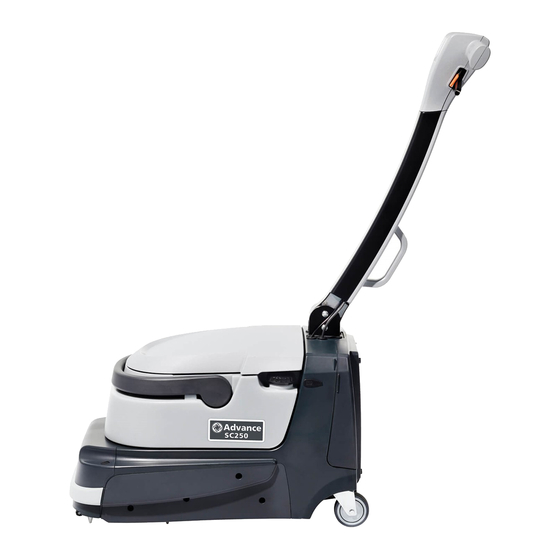
Page 15: Dimensions
03 - General Information Service Manual – SC250, Scrubtec 334, MA 30 Dimensions 16.7 in (425 mm) 24.8 in (630 mm) 48.8 in (1240 mm) 29.5 in (750 mm) Figure 6... -
Page 16: Scheduled Maintenance Table
03 - General Information Service Manual – SC250, Scrubtec 334, MA 30 Maintenance The lifespan of the machine and its maximum operating safety are ensured by correct and regular maintenance. Warning! Read carefully the instructions in the Safety chapter before performing any maintenance procedure. -
Page 17: 04 - Control System
Service Manual – SC250, Scrubtec 334, MA 30 04 - Control System 04 - Control System Functional Description The (electrical) functions of the machine are controlled The solution flow can be increased with 2 levels via the handlebar with the 3 buttons on the Main con- trol board (EB2) and activation of the hand presence sensors (S1 - S2) inside the grip handles (the position The corresponding green LEDs provide the... -
Page 18: Wiring Diagram
Service Manual – SC250, Scrubtec 334, MA 30 04 - Control System Wiring Diagram BATTERY+ MAIN CONTROL BOARD (EB2) RH HAND PRESENCE SENSOR (S1) Electronic board power supply + BUTTON.1 UI.8 UI.7 Start button input BUTTON.2 Power supply + EXT.1 UI.6 Power supply - EXT.2... -
Page 19: Component Locations
Service Manual – SC250, Scrubtec 334, MA 30 04 - Control System Component Locations • Main machine controller (EB1) • RH hand presence sensor (S1) • Main control board (EB2) • LH hand presence sensor (S2) Main machine controller (EB1) Figure 2 Main control board (EB2) -
Page 20: Removal And Installation
Service Manual – SC250, Scrubtec 334, MA 30 04 - Control System Removal and Installation Main Machine Controller (EB1) Warning! Electrostatic sensitive device, observe precautions for handling. Use the specific ESD gloves. The operator should not wear a sweater, fleece or other wool or synthetic clothing when changing the PCB. - Page 21 Service Manual – SC250, Scrubtec 334, MA 30 04 - Control System Main Machine Controller (EB1) (continues) Disconnect the connector for the water sensor wiring (C) Figure 6 Disconnect the connector for the BMS electronic battery management wiring (D) Figure 7...
- Page 22 Service Manual – SC250, Scrubtec 334, MA 30 04 - Control System Main Machine Controller (EB1) (continues) Disconnect the connector for the handlebar wiring (E) Figure 8 Disconnect the connector for the battery charger wiring (F) Figure 9...
- Page 23 Service Manual – SC250, Scrubtec 334, MA 30 04 - Control System Main Machine Controller (EB1) (continues) Disconnect the connector for the on button wiring (G) Figure 10 Disconnect the water pump connections wiring (H) Figure 11...
- Page 24 Service Manual – SC250, Scrubtec 334, MA 30 04 - Control System Main Machine Controller (EB1) (continues) 10 Disconnect the vacuum motor connections wiring (I) - While you unscrew the connection fastening screws, use a pair of pliers to hold the connector on the controller (when tighten the screw, use a tightening torque to a 0,4 Nm) Figure 12 11 Disconnect the brush motor connections wiring (J)
- Page 25 Service Manual – SC250, Scrubtec 334, MA 30 04 - Control System Main Machine Controller (EB1) (continues) 12 Disconnect the power supply connections wiring (K) - While you unscrew the connection fastening screws, use a pair of pliers to hold the connector on the controller (when tighten the screw, use a tightening torque to a 0,4 Nm) Figure 14 13 Remove the screws (L), then remove the main machine controller (when mounting, tighten the screws...
-
Page 26: Main Control Board (Eb2) And Hand Presence Sensors (S1, S2)
Service Manual – SC250, Scrubtec 334, MA 30 04 - Control System Main Control Board (EB2) and Hand Presence Sensors (S1, S2) Main Control Board Removal Open the rear cover and remove the battery Lower the handlebar and move it forwards by pressing the left lever Remove the 7 screws (A) and remove the lower cover (B) Figure 16 Remove the 3 upper cover (D) fastening screws (C) - Page 27 Service Manual – SC250, Scrubtec 334, MA 30 04 - Control System Main Control Board (EB2) and Hand Presence Sensors (S1, S2) (continues) Unscrew the screw (E) holding the main control board wiring (F) Figure 18 Disconnect the main wiring (G) and the 2 connections for the hand presence sensors (H) Figure 19...
- Page 28 Service Manual – SC250, Scrubtec 334, MA 30 04 - Control System Main Control Board (EB2) and Hand Presence Sensors (S1, S2) (continues) Carefully remove the main control board (I), detaching it from its seat on the front cover (J) Figure 20 Hand presence Sensors (S1, S2) Removal Disconnect the 2 connections wiring (K) from the hand presence sensors (L)
- Page 29 Service Manual – SC250, Scrubtec 334, MA 30 04 - Control System Main Control Board (EB2) and Hand Presence Sensors (S1, S2) (continues) Carefully remove the sensors (L), detaching them from their seat on the grip handles (N) Figure 22 Installation 10 Assemble the components in the reverse order of disassembly...
-
Page 30: Specifications
Service Manual – SC250, Scrubtec 334, MA 30 04 - Control System Specifications Main Machine Controller (EB1) Connectors BATTERY: type FCI T702035100J0G (2 ways, screw type) Description El. board in/out V ref. I max. Connected to Vbatt + BAT+ Vbatt - BAT- Figure 23 OUT1: type FCI T702035100J0G (2 ways, screw type) - Page 31 Service Manual – SC250, Scrubtec 334, MA 30 04 - Control System Main Machine Controller (EB1) Connectors (continues) OUT2: type FCI T702035100J0G (2 ways, screw type) Description El. board in/out V ref. I max. Connected to Vacuum motor output + Vacuum motor output - Figure 25 OUT3: faston 6.3x0.8mm (2 ways, vertical)
- Page 32 Service Manual – SC250, Scrubtec 334, MA 30 04 - Control System Main Machine Controller (EB1) Connectors (continues) CHARGE: JST B2P-VH(LF)(SN) (2 ways, vertical) Description El. board in/out V ref. I max. Connected to Battery charger input + Battery charger input - Figure 27 BATT: JST B5B-PH-K-S (5 ways, vertical) Description...
- Page 33 Service Manual – SC250, Scrubtec 334, MA 30 04 - Control System Main Machine Controller (EB1) Connectors (continues) BUTTON: JST B2B-EH-A (LF)(SN) (2 ways, vertical) Description El. board in/out V ref. I max. Connected to Power supply + <1A UI.J201.8 Power button input <1A UI.J201.7...
- Page 34 Service Manual – SC250, Scrubtec 334, MA 30 04 - Control System Main Machine Controller (EB1) Connectors (continues) C: JST B3B-ZR(LF)(SN) (3 ways, vertical) Description El. board in/out V ref. I max. Connected to Water sensor supply - <1A S3.1 Water sensor supply + <1A S3.2...
-
Page 35: Main Control Board (Eb2) Connectors
Service Manual – SC250, Scrubtec 334, MA 30 04 - Control System Main Control Board (EB2) Connectors J201: JST S8B-PH-SM4-TB (8 ways, vertical) Description El. board in/out V ref. I max. Connected to SPI clock 0-5V <1A EXT.6 SPI MOSI In-out 0-5V <1A... - Page 36 Service Manual – SC250, Scrubtec 334, MA 30 04 - Control System Main Control Board (EB2) Connectors (continues) LEFT: JST S3B-ZR-SM4A-TF (3 ways, side entry) Description El. board in/out V ref. I max. Connected to Left hand presence sensor supply - <1A S1.1 Left hand presence sensor supply +...
- Page 37 Service Manual – SC250, Scrubtec 334, MA 30 04 - Control System Main Control Board (EB2) Connectors (continues) EB2 (UI) BUTTONS (on EB2 side A) Type: 4 leg Dome 12mm Ø Ref. Description Power on/off button Vacuum system button Solution flow button EB2 (UI) LEDS (on EB2 side A) Type: Kingbright AM2520CGCK09 or equivalent Ref.
-
Page 38: Chassis System
Service Manual – SC250, Scrubtec 334, MA 30 10 - Chassis System 10 - Chassis System Chassis (main parts) Reference to Figure 1 • Plastic tank support chassis, solution system and recovery water system • Metal handlebar support chassis Metal handlebar support chassis and battery housing Plastic tank support chassis, solution system and... -
Page 39: 14 - Wheel System, Non Traction
Service Manual – SC250, Scrubtec 334, MA 30 14 - Wheel System, Non Traction 14 - Wheel System, Non Traction Functional Description The wheels assembly is composed by a pair of pivoting rear wheels and a pair of front wheels The front axle is fitted with a pedal mechanism for moving and parking the machine with the brush and squee- gee assembly lifted from the floor. -
Page 40: Specifications
Service Manual – SC250, Scrubtec 334, MA 30 14 - Wheel System, Non Traction Specifications Advance SC250, Clarke MA 30 Description / Model Nilfisk SC250, Scrubtec 334 Rear rotating wheel diameter 3 in (75 mm) Front wheel diameter 2 in (50 mm) -
Page 41: 24 - Electrical System
Service Manual – SC250, Scrubtec 334, MA 30 24 - Electrical System 24 - Electrical System Functional Description The machine electrical system is composed of the following components: • Lithium battery: the battery pack contains the • Main machine controller (EB1): it receives the lithium cell protection system (Battery Manage- controls from the Main control board (EB2) and ment System) and provides power (36Vdc nominal... -
Page 42: Wiring Diagram
Service Manual – SC250, Scrubtec 334, MA 30 24 - Electrical System Wiring Diagram BATTERY+ LITHIUM BATTERY + CONTROL SYSTEM (BAT + BMS) C1.C2 C1.B2 C1.A1 C1.C1 C1.B1 MAIN MACHINE CONTROLLER (EB1) BATT.1 Battery LED input - flashing BATT.2 Battery LED input - timed BATT.5 Battery LED input - data BATT.3 CAN-H (a1) BATT.4 CAN-L ( ) -
Page 43: Component Locations
Service Manual – SC250, Scrubtec 334, MA 30 24 - Electrical System Component Locations • Battery charger (CH) • Battery charger connection socket • Lithium battery (BAT) • Battery connector (C1) Battery charger connection socket Lithium battery (BAT) Battery charger (CH) Figure 2 Battery charger housing... -
Page 44: Maintenance And Adjustments
Service Manual – SC250, Scrubtec 334, MA 30 24 - Electrical System Maintenance and Adjustments Battery Installation Remove the rear cover on the battery compartment Grasp the battery handle, then push it downwards to seat it in place Battery Charging Caution! Charge the battery when only one LED of the battery symbol is light. -
Page 45: Battery Charge Level
Service Manual – SC250, Scrubtec 334, MA 30 24 - Electrical System Battery Charge Level The battery charge level can be viewed on the battery icon LEDs (5) The battery charge percentage depends on the number of LEDs lit, as shown in the figure 11. When the first left LED flashes (15%), the machine will only run for a few more minutes (this will depend on the characteristics of the work to perform) 100%... -
Page 46: Charging The Battery When Removed From The Machine
Service Manual – SC250, Scrubtec 334, MA 30 24 - Electrical System Charging the Battery when Removed from the Machine Remove the battery from the machine Place the battery in the appointed recharging area Connect the battery charger cable plug (B) into the battery socket (A) and the power supply cable plug into a mains socket (the mains voltage and frequency must be compatible with the battery charger values shown on the data plate) During charging, one of the 6 green LEDs on the battery (C) will remain steadily on to indicate the... -
Page 47: Display On Battery
Service Manual – SC250, Scrubtec 334, MA 30 24 - Electrical System Display on Battery Bu on 1 2 3 4 Figure 6 The battery pack contains the above “Display”, which • Red LED (Flashing): No charging consists of a Button to activate the display if not un- The battery cell temperature is lower than 0°C (32°F) der charge or discharge, 6 green LED’s to indicate the or higher than +50°C (+122°F) Charging will start... -
Page 48: Troubleshooting
Service Manual – SC250, Scrubtec 334, MA 30 24 - Electrical System Troubleshooting Trouble Possible Causes Remedy The machine is not working Battery (BAT) flat or connections faulty Charge the battery or clean the connections Battery (BAT) broken Check the battery no-load voltage The battery will not charge The battery charger (CH) is broken Replace... -
Page 49: Specifications
Service Manual – SC250, Scrubtec 334, MA 30 24 - Electrical System Specifications Advance SC250, Clarke MA 30 Description / Model Nilfisk SC250, Scrubtec 334 IP protection class Protection class (electric) Electrical system voltage 36Vdc Standard battery Lithium Ion - 36Vdc 8Ah Battery charger output 42Vdc 1÷2A... -
Page 50: Wiring Diagram
Service Manual – SC250, Scrubtec 334, MA 30 24 - Electrical System Wiring Diagram BRUSH BATTERY+ MAIN CONTROL MOTOR (M1) OUT1.+ Brush motor output BOARD (EB2) RH KNOB SENSOR (S1) Main controller power supply + BUTTON.1 UI.8 UI.7 Start button input BUTTON.2 LITHIUM BATTERY + Power supply +... -
Page 51: 30 - Solution System
Service Manual – SC250, Scrubtec 334, MA 30 30 - Solution System 30 - Solution System Functional Description The solution system supplies detergent to the brush when cleaning the floor. The solution tank is also part of the machine recovery tank. The solution flows from the tank to the valve before reaching the filter and the water pump (PM), and then to the solution dispensers in the brush compartment area The system also includes a water sensor (S3) which warns the operator when the solution tank is empty via the two washing push-button LEDs... -
Page 52: Wiring Diagram
Service Manual – SC250, Scrubtec 334, MA 30 30 - Solution System Wiring Diagram BATTERY+ MAIN MACHINE CONTROLLER (EB1) WATER SENSOR (S3) Water pump output OUT3.+ WATER PUMP (PM) Water pump output OUT3.- BATTERY- Figure 1... -
Page 53: Component Locations
Service Manual – SC250, Scrubtec 334, MA 30 30 - Solution System Component Locations • Solution tank assembly • Water Pump (PM) • Tank filler cap • Hoses • Tank valve • Water sensor (S3) • Solution filter • Solution dispenser to brush Solution tank filler plug Tank valve Solution tank... -
Page 54: Maintenance And Adjustments
Service Manual – SC250, Scrubtec 334, MA 30 30 - Solution System Maintenance and Adjustments Cleaning the Solution Tank and Filter Ensure that the machine is off Remove the tanks container from the machine body using the handle Lift the tank cover and remove the solution cap Rinse the tank out with water Remove the rubber gasket (A), then remove the filter strainer (B). -
Page 55: Solution Dispenser Cleaning
Service Manual – SC250, Scrubtec 334, MA 30 30 - Solution System Solution Dispenser Cleaning Ensure that the machine is off Remove the tanks container from the machine body using the handle Lift the machine body to access the lower part of the cleaning deck Remove the cylindrical brush Disassemble the solution dispensers (A) and clean them with water and detergent, then rinse and reassemble in the corresponding housings... -
Page 56: Troubleshooting
Service Manual – SC250, Scrubtec 334, MA 30 30 - Solution System Troubleshooting Trouble Possible Causes Remedy The solution push-button LEDs flash Solution tank empty Fill the tank Small amount of solution or no solution Solution dispensers clogged. Clean the solution dispensers. reaches the brush Solution filter clogged/dirty Clean the filter... - Page 57 Service Manual – SC250, Scrubtec 334, MA 30 30 - Solution System Water Pump Voltage and Cleaning Check (continues) On the main machine controller , identify the two output water pump faston connections (C) With a digital multimenter (D) set to AC input (E), verify that on the output water pump (C) is current an alternating voltage of ~ 14 ÷...
- Page 58 Service Manual – SC250, Scrubtec 334, MA 30 30 - Solution System Water Pump Voltage and Cleaning Check (continues) Water Pump Cleaning/Unlocking Blow in the Water pump duct (F) with the compressed air at 1 bar max (for the Water pump removal see the procedure in Water pump removal/installation paragraph), Caution! Blow with compressed air on the arrow direction as shown on the pump label.
-
Page 59: Removal And Installation
Service Manual – SC250, Scrubtec 334, MA 30 30 - Solution System Removal and Installation Solution Tank Valve Remove the tank assembly from the machine Working at the workbench, rotate the tank assembly and Remove the 2 screws (A), remove the valve (B) and retain the gasket (C) for reuse Figure 6... -
Page 60: Water Pump
Service Manual – SC250, Scrubtec 334, MA 30 30 - Solution System Water Pump Removal Remove the tank assembly from the machine Open the rear cover and remove the battery Remove the 7 caps (A) and remove the 7 screws (B), then remove the upper cover from the machine body Figure 7 Disconnect the connection (D) and remove the Water pump (E), retaining the brackets and hoses for reuse... -
Page 61: Water Sensor
Service Manual – SC250, Scrubtec 334, MA 30 30 - Solution System Water Sensor Removal Remove the tank assembly from the machine Open the rear cover and remove the battery Remove upper cover from the machine body (A) Figure 9 Remove the 2 screws (A) and lift the cover (B) off the sensor bracket Disconnect the connection (C) and remove the water sensor (D) from the bracket Figure 10... -
Page 62: Specifications
Service Manual – SC250, Scrubtec 334, MA 30 30 - Solution System Specifications Advance SC250 / Clarke MA 30 / Nilfisk Description / Model SC250, Scrubtec 334 Solution tank capacity 1.6 US gal (6 liters) Min/max solution flow 0.04 / 0.08 US gal/min (0.15 / 0.3 L/min) -
Page 63: 34 - Scrub System
Service Manual – SC250, Scrubtec 334, MA 30 34 - Scrub System 34 - Scrub System Functional Description The scrub system is enabled when the machine is In the event of brush motor overload, a safety system turned on stops the brushes after about 25 seconds of continu- The cylindrical brush rotates in the direction of travel ous overload machine... -
Page 64: Wiring Diagram
Service Manual – SC250, Scrubtec 334, MA 30 34 - Scrub System Wiring Diagram BATTERY+ BRUSH OUT1.+ Brush motor output MOTOR (M1) OUT1.- Brush motor output MAIN MACHINE CONTROLLER (EB1) BATTERY- Figure 1... -
Page 65: Component Locations
Service Manual – SC250, Scrubtec 334, MA 30 34 - Scrub System Component Locations • Brush motor (M1) • Casing • Cylindrical brush • Floor brush pressure adjustment knob • Drive hub • Debris collection tank • Driving belt Cylindrical brush Drive hub Debris collection tank Brush motor (M1) -
Page 66: Maintenance And Adjustments
Service Manual – SC250, Scrubtec 334, MA 30 34 - Scrub System Maintenance and Adjustments Brush and Brush Compartment Cleaning Ensure that the machine is off Remove the tanks container from the machine body using the handle Lift the machine body to access the lower part of the cleaning deck Turn the lever counter-clockwise (A) and remove the brush Clean and wash the cylindrical brush with water and detergent Check the brush bristles for integrity and wear;... -
Page 67: Troubleshooting
Service Manual – SC250, Scrubtec 334, MA 30 34 - Scrub System Troubleshooting Trouble Possible Causes Remedy The brush does not clean properly The brush is excessively worn Replace The battery LEDs flash while working Brush motor overload Reduce the brush pressure on the floor There are foreign materials (tangled threads, etc.) Clean the brush hub... -
Page 68: Brush Motor Amperage Check
Service Manual – SC250, Scrubtec 334, MA 30 34 - Scrub System Brush Motor Amperage Check Warning! This procedure must be performed by qualified personnel only. Open the rear cover on the battery compartment Remove the screw (A) and remove the controller protective cover (B) Figure 5... - Page 69 Service Manual – SC250, Scrubtec 334, MA 30 34 - Scrub System Brush Motor Amperage Test (continues) Apply the amp clamp (C) to the electrical cable (D) of the brush motor Switch on the machine and operate it with one hand on the handlebar Check that the brush motor current draw is no more than 1 A at 36 V If the current draw is higher, check the belt tension or remove the brush motor (see the procedure in the Vacuum System Motor Disassembly/Assembly paragraph), and check the condition of all its components...
-
Page 70: Removal And Installation
Service Manual – SC250, Scrubtec 334, MA 30 34 - Scrub System Removal and Installation Driving Belt Check the tension of the belt (C) between motor Check and brush using the TEN-SIT (D) device: When Remove the tank assembly from the machine deflecting the centre of the belt (E), the tool should measure a value of 69Hz ±10 Open the rear cover and remove the battery... - Page 71 Service Manual – SC250, Scrubtec 334, MA 30 34 - Scrub System Driving Belt (continues) Replacement If the belt (C) requires replacement, loosen the 3 screws (F) and move the brush motor and pulley (G) to loosen the belt, then replace it Tension the belt (see the procedure given above) Figure 9 Reassembly...
-
Page 72: Brush Motor
Service Manual – SC250, Scrubtec 334, MA 30 34 - Scrub System Brush Motor Removal Remove the tank assembly from the machine Open the rear cover and remove the battery Remove the cylindrical brush Remove the screw to remove the controller protective cover Disconnect the brush motor connections (A) - Do not loosen the connection fastening screws, use a pair of pliers to hold the connector on the controller... - Page 73 Service Manual – SC250, Scrubtec 334, MA 30 34 - Scrub System Brush Motor (continues) Remove the 7 caps (C) and remove the 7 screws (D), then remove the upper cover from the machine body Figure 12 Remove the screw (F), keeping the inner locknut (G) held in position Remove the 2 screws (H), keeping the inner locknuts (I) held in position Figure 13 Working underneath the machine, remove the clamp (J) and extract the wiring Remove the motor and...
- Page 74 Service Manual – SC250, Scrubtec 334, MA 30 34 - Scrub System Brush Motor (continues) 10 Working at the workbench, remove the 4 screws (L), then remove the brush motor (M) from its support Figure 15 Installation 11 Fit the brush motor on its support and tension the belt 12 During assembly on the machine, position the brush motor and keep it rotated as shown (N), then screw in and tighten the 3 screws (O) with the locknuts Figure 16...
-
Page 75: Specifications
Service Manual – SC250, Scrubtec 334, MA 30 34 - Scrub System Specifications Advance SC250, Clarke MA 30 Description / Model Nilfisk SC250, Scrubtec 334 Cleaning width 13.4 in (340 mm) Cylindrical brush diameter 3 in (80 mm) Brush pressure on the ground... -
Page 76: 38 - Squeegee System
Service Manual – SC250, Scrubtec 334, MA 30 38 - Squeegee System 38 - Squeegee System Functional Description The squeegee system cleans the liquid off the floor, which is then collected by the recovery system. The squeegee assembly (A) is attached to the machine body via two quick fix brackets fitted with springs, which allow the squeegees to adhere to and apply the correct pressure to the floor, even if it is not perfectly smooth and level Operating the right-hand lever on the handlebar lifts the front squeegee, allowing larger debris to be picked... - Page 77 Service Manual – SC250, Scrubtec 334, MA 30 38 - Squeegee System Component Locations • Squeegee assembly • Quick coupling • Integrated brackets with return spring for floor pressure • Front right squeegee lifting lever • Mechanism for front squeegee lifting and vacuum system stop Integrated brackets with return spring for floor pressure...
-
Page 78: Maintenance And Adjustments
Service Manual – SC250, Scrubtec 334, MA 30 38 - Squeegee System Maintenance and Adjustments Squeegee Bar Cleaning Note: The squeegee bars must be clean and the blades must be in good conditions in order to get a good drying. Caution! It is advisable to wear protective gloves when cleaning the squeegee bars because there can be sharp debris. -
Page 79: Troubleshooting
Service Manual – SC250, Scrubtec 334, MA 30 38 - Squeegee System Troubleshooting Trouble Possible Causes Remedy Dirty water vacuuming is insufficient or The squeegee bars are dirty or the blades are worn or Clean and check the squeegee damaged. bars. -
Page 80: Removal And Installation
Service Manual – SC250, Scrubtec 334, MA 30 38 - Squeegee System Removal and Installation Vacuum Duct Removal Remove the tank assembly from the machine Open the rear cover and remove the battery Remove upper cover from the machine body (A) Figure 4 Loosen the nut and locknut (B) and remove the squeegee lifting cable (C) Figure 5... - Page 81 Service Manual – SC250, Scrubtec 334, MA 30 38 - Squeegee System Vacuum Duct (continues) Unscrew the 4 screws (D) and lift the vacuum duct bracket (E) Figure 6 Free the front hook (F) from the linkage (G), then remove the vacuum duct bracket (E) Remove the vacuum duct (H) and check that the openings are free of dirt and debris Figure 7...
- Page 82 Service Manual – SC250, Scrubtec 334, MA 30 38 - Squeegee System Vacuum Duct (continues) Installation Install the vacuum duct, making sure that the front (I) and rear openings (J) are correctly installed on the chassis Figure 8 Fasten the front bar hook (K) to the squeegee lifting linkage (L), then fit the lifting cable (M), reinstalling the closing nut and locknut (N) Figure 9...
- Page 83 Service Manual – SC250, Scrubtec 334, MA 30 38 - Squeegee System Vacuum Duct (continues) 10 Adjust squeegee lifting: Press the lifting lever and stop it with the orange push-button 11 The minimum height of the lifting bar must be ≥ 0.7 in (≥ 18 mm) (O). Adjust with the nut and locknut 0.7 in (18 mm) 0.7 in (18 mm) Figure 10...
-
Page 84: Specifications
Service Manual – SC250, Scrubtec 334, MA 30 38 - Squeegee System Specifications Advance SC250, Clarke MA 30 Description / Model Nilfisk SC250, Scrubtec 334 Squeegee width 14 in (360 mm) -
Page 85: 40 - Recovery System
Service Manual – SC250, Scrubtec 334, MA 30 40 - Recovery System 40 - Recovery System Functional Description The recovery water system removes the dirty water The gasket on the input of the vacuum system motor from the floor and pipes it to a recovery tank. When allows full functionality of the system, while the filter the machine is running, the dirty water on the floor is built in the gasket prevents the passage of dirt and... -
Page 86: Component Locations
Service Manual – SC250, Scrubtec 334, MA 30 40 - Recovery System Component Locations • Recovery tank assembly • Vacuum grid with automatic shut-off float • Vacuum sleeve from squeegee • Vacuum system motor (M2) • Vacuum sleeve from grid with automatic shut-off •... -
Page 87: Maintenance And Adjustments
Service Manual – SC250, Scrubtec 334, MA 30 40 - Recovery System Maintenance and Adjustments Recovery Tank and Cover Cleaning Lift the tanks container from the machine body If necessary, replace the gasket (D) by removing using the handle, and take it to the designated it from its housing on the cover When disposal area assembling the new gasket, install the joint (E) -
Page 88: Air Filter, Gaskets And Recovery Water Duct Cleaning
Service Manual – SC250, Scrubtec 334, MA 30 40 - Recovery System Air Filter, Gaskets and Recovery Water Duct Cleaning Remove the tanks container from the machine body using the handle Remove the air filter (A) and clean it. Refit the filter in the housing of the gasket (B). Note: The gaskets (B) and (C) allow the creation of the vacuum in the system which is necessary to collect the recovery water. -
Page 89: Troubleshooting
Service Manual – SC250, Scrubtec 334, MA 30 40 - Recovery System Troubleshooting Trouble Possible Causes Remedy The vacuum system motor will not turn on Wiring between Main machine controller (EB1) and Repair vacuum system motor (M2) damaged Main control board (EB2) faulty Replace Vacuum system motor faulty Check the current draw/Replace... -
Page 90: Vacuum System Motor Amperage Test
Service Manual – SC250, Scrubtec 334, MA 30 40 - Recovery System Vacuum System Motor Amperage Test Warning! This procedure must be performed by qualified personnel only. Open the rear cover on the battery compartment Remove the screw (A) and remove the main machine controller protective cover (B) Figure 6... - Page 91 Service Manual – SC250, Scrubtec 334, MA 30 40 - Recovery System Vacuum System Motor Amperage Test (continues) Apply the amp clamp (C) to the electrical cable (D) of the vacuum system motor Switch on the machine and operate it with one hand on the handlebar Check that the vacuum system motor current draw is between 5 5 and 6 5 A at 36 V If the current draw is higher, remove the vacuum system motor (see the procedure in the Vacuum System Motor Disassembly/Assembly paragraph), and check the condition of all its components to detect...
-
Page 92: Removal And Installation
Service Manual – SC250, Scrubtec 334, MA 30 40 - Recovery System Removal and Installation Vacuum System Motor Removal Remove the tank assembly from the machine Open the rear cover and remove the battery Remove the screw to remove the controller protective cover Disconnect the vacuum motor connections (A) - Do not loosen the connection fastening screws, use a pair of pliers to hold the connector on the controller... - Page 93 Service Manual – SC250, Scrubtec 334, MA 30 40 - Recovery System Vacuum System Motor (continues) Turn the machine over onto its right side to access the lower area Remove clamp (C) and clamp (D) to free up the wiring Figure 10 Remove the wiring (E) from the machine Unscrew the 4 retaining screws (F) and remove the vacuum motor unit (G) from the machine...
- Page 94 Service Manual – SC250, Scrubtec 334, MA 30 40 - Recovery System Vacuum System Motor (continues) Disassembly 10 At the workbench, unscrew the 4 screws (H), then carefully rotate the vacuum system assembly 11 Remove the clamp (I) Figure 12 12 Lift the outer container (J) out of the inner container (K), then extract the motor (L) Figure 13...
- Page 95 Service Manual – SC250, Scrubtec 334, MA 30 40 - Recovery System Vacuum System Motor (continues) 13 Save the gaskets (M) and (N) Figure 14 14 Remove the save the clamp (O) and the dividing sponge (P), then disconnect the connections (Q) Figure 15 15 Clean the inside of the containers to remove any dirt which has accumulated, and check all gaskets for wear;...
- Page 96 Service Manual – SC250, Scrubtec 334, MA 30 40 - Recovery System Vacuum System Motor (continues) Assembly 16 Position the gasket (M) on the vacuum system motor Check that the gasket is reassembled with the correct orientation (slots) 17 Install the clamp (R) The clamp must be positioned at 2 2 in (55 mm) from the upper surface, around the entire circumference 2.2 in (55 mm) Figure 16...
- Page 97 Service Manual – SC250, Scrubtec 334, MA 30 40 - Recovery System Vacuum System Motor (continues) 21 Run the wiring (E) inside the large hole in the outer container (J) 22 Insert the vacuum system motor in the outer container, as shown (S) Figure 18 23 Rotate the outer container with the vacuum system motor Check that the motor and gasket are positioned almost in line with the outer edge of the container...
-
Page 98: Specifications
Service Manual – SC250, Scrubtec 334, MA 30 40 - Recovery System Specifications Advance SC250, Clarke MA 30 Description / Model Nilfisk SC250, Scrubtec 334 Recovery tank capacity 1.6 US gal (6 liters) Power 0.24 hp (180 W) Maximum current 6 ±0.3 A... -
Page 99: 90 - Options
Service Manual – SC250, Scrubtec 334, MA 30 90 - Options 90 - Options Description Illustration BATTERY AND BATTERY CHARGER KIT (All versions) Battery Battery charger Power supply cables...
Need help?
Do you have a question about the Advance SC250 and is the answer not in the manual?
Questions and answers