Table of Contents
Advertisement
Quick Links
HOBO® MicroRX Station for HOBOnet® (RX2105 and RX2106) Manual
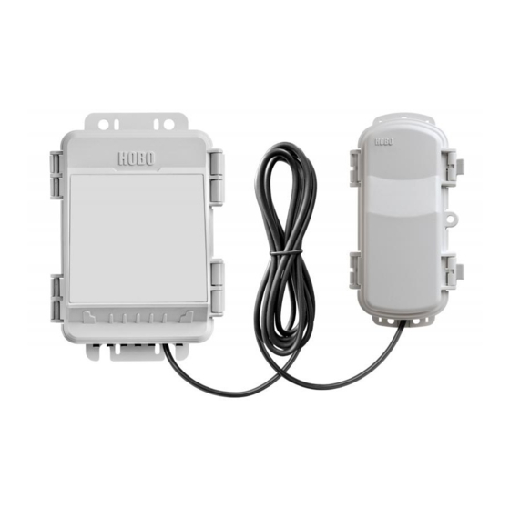
RX2105 model shown
HOBO MicroRX Station for
HOBOnet
Models:
RX2105 MicroRX Station
RX2106 MicroRX Station with
Solar Panel
RX210x‐900 (US)
RX210x‐868 (Europe)
RX210x‐922 (Australia/NZ)
Included Items:
RX Manager
Grease packet
Screws and washers
Cable ties
Six AA lithium batteries and
AC adapter (P‐AC‐1) with
RX2105
Rechargeable battery pack
with RX2106
Required Items:
HOBOlink
HOBOnet RXW motes
Optional Items:
Smart sensors
Ground wire (CABLE‐
MICRO‐G)
2‐meter tripod (M‐TPB)
3‐meter tripod (M‐TPA)
1.5 meter mast (M‐MPB)
1‐5/8 inch U‐bolts (U‐BOLT‐
KIT2)
Guy wire kit (M‐GWA)
1/2 inch stake kit (M‐SKA)
Sensors and accessories are
available at
www.onsetcomp.com.
24500‐A
The HOBO MicroRX Station for HOBOnet provides continuous logging for both indoor and
outdoor environments with wireless sensor motes and up to five smart sensors. Logged data
from the station is transferred at regular connection intervals to HOBOlink® web‐based
software where you can check the latest conditions, view graphs, configure sensors and alarms,
set up a dashboard, download your data, or schedule data delivery via email or FTP. This
durable, compact station has a built‐in LCD screen to check the current system configuration
and status, start and stop logging, add and remove sensors, and connect to HOBOlink on
demand. The station offers two primary power source options depending on your deployment
needs: the RX2105 model includes user‐replaceable AA lithium batteries and an AC adapter
while the RX2106 model is designed with a built‐in solar panel and rechargeable NiMH battery
pack.
Specifications
Station
Operating Range
Smart Sensor Connectors
Smart Sensor Network Cable
Length
Smart Sensor Data Channels
Logging Rate
Time Accuracy
Battery Type/Power Source
Battery Life/Power Source
Alarm Notification Latency
Enclosure Access
LCD
Materials
RX2105: ‐40° to 60°C (‐40° to 140°F)
RX2106: ‐20° to 60°C (‐4° to 140°F)
5
100 m (328 ft) maximum
Maximum of 15 (some smart sensors use more than one data
channel; see sensor manual for details)
1 minute to 18 hours
±8 seconds per month in 0° to 40°C (32°F to 104°F) range;
±30 seconds per month in ‐40° to 60°C (‐40° to 140°F) range
RX2105: AC power adapter (P‐AC‐1) and 6 AA 1.5 V lithium batteries
RX2106: Integrated 1.7 watt solar panel and NiMH rechargeable
battery pack; optional AC power adapter (P‐AC‐1) or external solar
panel (SOLAR‐xW) can be used in place of integrated solar panel
RX2105:
Runs continuously with the included AC adapter.
Batteries can be used as a backup to AC power; battery life of 3
months with 1 minute logging and daily connections or 2 months
with 1 minute logging and hourly connections, and with
approximately 10 motes. Note: Deployments in areas with weak
cellular strength could reduce battery life.
RX2106:
Typical 3–5 years when operated in the temperature range ‐20° to
40°C (‐4° to 104°F); operation outside this range will reduce the
battery service life.
Maximum connection rates with built‐in solar panel, in full sun:
10 minute connections year round for latitudes less than ±40°
10 minute connections through three seasons in other regions,
reduced to 30 minute connections in winter
Maximum connection rates with external 5W or 15W solar panels:
10 minute connections year round, in full sun
Connection rate with external solar panels may be less if
deployed in partial sun
Battery life of 1 month without solar recharging, with hourly
connections, 1 minute logging, and approximately 10 motes.
Logging interval plus 2–4 minutes, typical
Hinged door secured by two latches with eyelets for use with user‐
supplied padlocks
LCD is visible from 0° to 50°C (32° to 122°F); the LCD may react
slowly or go blank in temperatures outside this range
Outer enclosure: Polycarbonate/PBT blend with brass inserts;
Interior: Polycarbonate/PBT; Gasket: Silicone foam; Cable channel:
Santoprene™ TPE; U‐Bolts (not included): Steel with zinc dichromate
finish
Advertisement
Table of Contents

Subscribe to Our Youtube Channel
Related Manuals for Onset Hobo MicroRX RX2105


Summary of Contents for Onset Hobo MicroRX RX2105
- Page 1 HOBO® MicroRX Station for HOBOnet® (RX2105 and RX2106) Manual The HOBO MicroRX Station for HOBOnet provides continuous logging for both indoor and outdoor environments with wireless sensor motes and up to five smart sensors. Logged data from the station is transferred at regular connection intervals to HOBOlink® web‐based software where you can check the latest conditions, view graphs, configure sensors and alarms, set up a dashboard, download your data, or schedule data delivery via email or FTP. This durable, compact station has a built‐in LCD screen to check the current system configuration and status, start and stop logging, add and remove sensors, and connect to HOBOlink on demand. The station offers two primary power source options depending on your deployment needs: the RX2105 model includes user‐replaceable AA lithium batteries and an AC adapter while the RX2106 model is designed with a built‐in solar panel and rechargeable NiMH battery RX2105 model shown pack. Specifications Station HOBO MicroRX Station for Operating Range RX2105: ‐40° to 60°C (‐40° to 140°F) HOBOnet RX2106: ‐20° to 60°C (‐4° to 140°F) Smart Sensor Connectors 5 Models: Smart Sensor Network Cable 100 m (328 ft) maximum RX2105 MicroRX Station Length RX2106 MicroRX Station with Smart Sensor Data Channels Maximum of 15 (some smart sensors use more than one data Solar Panel channel; see sensor manual for details) RX210x‐900 (US) Logging Rate 1 minute to 18 hours RX210x‐868 (Europe) RX210x‐922 (Australia/NZ) Time Accuracy ...
- Page 2 HOBO MicroRX Station for HOBOnet (RX2105 and RX2106) Manual Specifications (continued) 5.3 cm (2.1 in.) Dimensions 19.95 x 13.68 x 7.49 cm (7.85 x 5.39 x 2.95 in.); see diagrams at left 3.2 cm Weight 678 g (23.9 oz) (1.25 in.) Mounting Optional U‐bolts are compatible with masts up to 4.14 cm (1.63 in.) mast diameter; can also be mounted with zip ties or mounted to a flat surface with screws Environmental Rating Weatherproof enclosure, NEMA 4X and IP66 (requires proper installation of cable channel system) Wireless Radio GSM/GPRS/EDGE: Quad band 850/900/1800/1900 MHz UMTS/HSPA+: Seven band 800/850/900/1800/1900/2100 MHz 19.95 cm LTE: Twelve Band 700/800/850/900/1800/1900/2100/2600 MHz (7.85 in.) Antenna 4G LTE The CE Marking identifies this product as complying with all relevant directives in the European Union (EU) See last page, FCC ID QIPPLS62‐W, IC ID:7830A‐PLS62W Manager 13.68 cm Operating Range ‐25° to 60°C (‐13° to 140°F) (5.39 in.) ...
- Page 3 HOBO MicroRX Station for HOBOnet (RX2105 and RX2106) Manual Station Door: This is the protective, hinged door covering the Device Components and Operation LCD and electronics. The station serial number and device key Station Door needed for HOBOlink registration are located on the inside of the door. Battery Holder: The location where batteries are installed (AA 1.5 V lithium batteries for RX2105 models or a NiMH battery pack for RX2106 models); see both Battery Information sections. Manager: The mote connected to the station that transmits and receives data to and from wireless motes in the network. Micro SIM Card: This enables cellular communications. USB Port: Use this port to connect the station to the computer via USB cable as needed for HOBOware® if you are installing Manager your own micro SIM card or for data offload to CSV file. Battery Holder LCD Screen: This shows details about system, module, and sensor operation (see LCD Operation). RX2105 model shown Solar Panel Port: In RX2106 models, use this port to plug in the built‐in solar panel or an external solar panel with a higher Micro SIM wattage (see Setting up the Station). Card Select Button Battery Port: Use this port to plug in the internal battery cable USB Port (see Setting up the Station and both Battery Information Start/ sections). Stop AC Adapter Port: Use this port to plug in an AC adapter (see Button both Battery Information sections). ...
-
Page 4: Lcd Operation
HOBO MicroRX Station for HOBOnet (RX2105 and RX2106) Manual Mounting Tab Mounting Tab: Use the tabs at the top and bottom of the mote to mount it (see Deployment Guidelines). Antenna Cable: Use this cable to connect the manager to the station. Latch Eyelet: Use this eyelet to attach a 3/16 inch padlock to the mote for security. Eyelet Latch: Use the two latches to open and close the mote door. Antenna: This is the built‐in antenna for the radio communications across the wireless network. USB Port USB Port: Use this port to connect to the mote to a computer via USB cable if you need to update the firmware (see Updating Cable Manager Firmware). Manager LCD Operation This example shows all symbols illuminated on the LCD screen with an overview of what each section of the LCD represents. Refer to the table below for details about each section and associated symbols. Logging Status System Status Battery and Memory Status Connection Status Channel and Device Information Manager Status Button Symbols System Status This part of the LCD shows the overall system status. When the station is powered up, “Initializing System” flashes in the upper left part of the LCD. After initialization is ... - Page 5 9 channels are shown on the main screen as shown. are 5 smart sensor channels. Module 2 When viewing the module 2 screen, information about the manager is displayed. The channel count represents all measurement channels plus a battery channel for each mote in the wireless network. For example, one temperature/RH wireless sensor and one repeater has a channel count of four as shown at right. This will blink in the lower right part of the LCD when a firmware update is underway. It will display which module or element is being updated. This is a numerical code that appears when a system fault has occurred. You may need to provide this code to Onset Technical Support. See Troubleshooting for details. This is the version number of the station firmware. It only appears when powering up the device. Button Symbols Use the three buttons below the following symbols to operate the station. Press any of the three buttons to turn on the LCD. Press this button to cycle through status information about the smart sensors and module 2. Press this button to start logging. This option is not available while the station is actively connected to HOBOlink. Press this button to stop logging. This option is not available while the station is actively connected to HOBOlink. Press this button to connect to HOBOlink. This option is only available on the main LCD screen. It is not available when scrolling through smart sensor and module information with the Select button. In addition, this option is not available while a connection is underway or active. Press this Search button for the station to detect all currently installed smart sensors or add motes to your wireless ...
-
Page 6: Setting Up The Station
HOBO MicroRX Station for HOBOnet (RX2105 and RX2106) Manual Plug in solar Notes on LCD Operation: panel cable The LCD will turn off after 5 minutes of inactivity. Press here in any button to turn the LCD back on. RX2106 models There can be a delay before the LCD updates. For example, if you plug in an AC adapter, it may take a few seconds before the lightning bolt icon appears on the LCD. This delay is by design to preserve battery life. Connect the battery cable here Setting up the Station Follow these steps to set up the station. b. Once the battery cable is plugged in, “Initializing System” will flash on the LCD. A checkmark appears 1. Log into HOBOlink. next to “System” after the station initialization is Go to www.hobolink.com and log into an existing account complete. or create a new one. You’ll receive an email to activate the new account. 2. Register the station. “Initializing In HOBOlink, click Devices, then RX Devices, and click the System” Register a Device link. Give the station a name and enter flashes when the battery ... - Page 7 HOBO MicroRX Station for HOBOnet (RX2105 and RX2106) Manual b. Install the batteries in the mote and press the button on the mote for 3 seconds. Use the Next button to save changes and move through each configuration screen Press this button on the mote for 3 seconds Or, you can choose a specific item to configure c. Watch the mote LCD during the process of joining the from this menu network. Readout Configuration i. a. Click Readout from the Configuration menu. ii. b. Set the connection interval, which is how often the station will connect to HOBOlink. The minimum connection interval depends on your communication plan. This signal strength icon Once a network is found, c. If you wish to set up a second connection interval, select blinks while searching for the icon will stop flashing the “Night mode” checkbox. Select when night mode a network. and the bars will cycle from ...
- Page 8 HOBO MicroRX Station for HOBOnet (RX2105 and RX2106) Manual b. Select the logging interval to be used for all wireless Tip: When a sampling interval is configured, the station sensors, which can be different than the one used for will take multiple measurements within a given logging smart sensors (if applicable). interval and then average them together to create a single logged data point. This is only an option for the following smart sensors that support measurement averaging: temperature (S‐TMB‐M0xx), PAR (S‐LIA‐ M003), solar radiation (S‐LIB‐M003), barometric pressure (S‐BPA‐CM10 and S‐BPB‐CM50), 4‐20mA input (S‐CIA‐CM14), 12‐bit voltage input (S‐VIA‐CM14), and FlexSmart TRMS module (S‐FS‐TRMSA‐D). Disable the sampling interval if none of your smart sensors support measurement averaging to avoid unnecessary drain on the battery power. c. Click Save or Next. d. Click Save or click Next. d. Click one of the motes from the menu under Module 2: Wireless Sensors Logging as shown in the following example. Click the serial number or name for the mote, not the measurement type. e. Click a smart sensor from the Configuration menu. f. Type a label for the smart sensor (optional) and click to e. Type a label for the mote (optional) and click to enable enable or disable the graph (enabled by default). the battery graph for the mote if desired. The label will g.
- Page 9 HOBO MicroRX Station for HOBOnet (RX2105 and RX2106) Manual 7. Start logging. the last connection. You can also view any enabled graphs as shown in the following example. Press the Start button on the station to start logging. The station will connect to HOBOlink (“Connection” will blink on the LCD) and then logging will begin at the logging interval specified for smart sensors (if applicable) and wireless sensors. Logged data is saved in a database. You can export this data on demand as needed or set up automatic exports that are Press this button to start logging delivered to email and/or FTP addresses on a schedule you You can also start logging from HOBOlink. Select specify. Start/Stop from the Configure menu in HOBOlink and click To download and export data: Start. Logging will not begin until the next time the station 1. In HOBOlink, click Data and then Exports. connects to HOBOlink. Press the Connect button on the 2. Click Create New Export. station to connect to HOBOlink at any time. 3. Follow the instructions on the screen to select the name, Once logging begins, “Logging” appears in the upper right format, time zone, and time frame, and then the devices corner of the LCD as shown in the following example. and sensors to include in the export. Reorder the sensors as “Logging” will blink until the first logging sample is needed. recorded. At that point, it will stop blinking and remain 4. Click Save to keep these settings for future use or click illuminated until logging is stopped. ...
- Page 10 For all other sensors and channels: Select whether the alarm should trip above or below a value or outside a b. Set the length of time for HOBOlink to wait after the range. Enter the sensor reading(s) for the alarm station has missed a connection before an alarm trips. threshold. Enter the number of logged data points you c. Select the action to be taken when this alarm trips: send want the station to record before the alarm trips. an email or text. Enter the details and then select “Send d. If you selected the alarm to trip above or below a on Clear Also” if you want an email or text when the specific reading, then select when the alarm should alarm clears as well. clear: above or below the same value or a different Important: Standard data fees and text messaging rates value. Enter the value if necessary. may apply when using text notifications. Onset does not 4. Select the action to be taken when the alarm trips: send an charge a fee or guarantee delivery of text alerts, which is email or text. Enter the details and then select “Send on subject to your carrier’s service and location. See the Clear Also” if you want an email or text when the alarm HOBOlink Help for additional details on alarm clears as well. notifications. Important: Standard data fees and text messaging rates d. Click Add Action if you want multiple actions to be taken may apply when using text notifications. Onset does not when the alarm trips (for example send an email and a charge a fee or guarantee delivery of text alerts, which is text). subject to your carrier’s service and location. See the 4. For Battery Low and Sensor Failure alarms: ...
-
Page 11: Starting And Stopping Logging
HOBO MicroRX Station for HOBOnet (RX2105 and RX2106) Manual then it will be 4 hours before an alarm clear message is sent of silicone grease. Push each new sensor cable into the hole after the alarm is triggered‐‐unless enough rain has continued that lines up with the corresponding sensor connector. Use to accumulate that causes the alarm to trip again. the integrated plugs in the cable channel to fill any empty holes. Starting and Stopping Logging 4. Press the Select button to view the smart sensors on the LCD screen. You can start and stop logging with the Start/Stop button on the station or from HOBOlink. To start and stop logging with the station: 1. When the station is stopped, press the Start button to start logging. The device will connect to HOBOlink (“Connection” will blink on the LCD) and then logging will begin at the logging interval specified for smart sensors (if applicable) and wireless sensors. The station is stopped Press the Search button for the station Press the Select button to view to find all connected smart sensors the smart sensor screen 5. Press the Search button for the station to detect all the smart sensors currently connected (the magnifying glass icon should be visible as in the previous example). 6. Press the Start button to begin logging again. The station will automatically connect to HOBOlink. Press this button to start logging 7. Make sure the cable channel is securely in place and close the station door. ... - Page 12 HOBO MicroRX Station for HOBOnet (RX2105 and RX2106) Manual 3. Press the Search button (the magnifying glass). The 7. Repeat steps 4–6 for any additional motes to add. magnifying glass icon will blink while the station is in search 8. Press the Search button (the magnifying glass) on the mode. station to stop searching for motes. Press this button so the station is ready to have motes join the network Press this button again to 4. Open the mote door and install the batteries if you have not stop searching for motes already done so. Measurements will be recorded at the logging interval specified in HOBOlink, transmitted to the station, and uploaded to 5. Press the button on the mote for 3 seconds. The signal HOBOlink at the next connection interval (readout). strength icon will flash and then cycle. To remove a mote from the network: a. In HOBOlink, click Devices, then RX Devices, and find the station with the mote you want to delete. Click the arrow next to and select Module/Sensor Configuration. b. Select the mote serial number or name from the Configuration menu as shown in the following example. Press this button for 3 seconds for the mote to join ...
-
Page 13: Deployment Guidelines
HOBO MicroRX Station for HOBOnet (RX2105 and RX2106) Manual 1. Click Devices and then RX Devices, and find the station you RX2106 models as it is charged and the antenna in both models will not have optimal range. want to configure. Click the arrow next to on the If possible, avoid sites immediately adjacent to Devices page and select Readout Configuration. radio/television/microwave towers and equipment. In rare 2. Set the connection interval. The minimum connection situations, strong electromagnetic interference may result interval depends on your communication plan. in sensor network errors. 3. If you wish to set up a second connection interval, select If you are using a wind speed/direction sensor or if the the “Night Mode” checkbox. Select when night mode station will be installed on a roof or in a location with should begin and end and then enter the connection exposure to lightning, use a grounding wire (CABLE‐ interval you want to use during that part of the day. MICRO‐G). A grounding wire may also reduce potential 4. Click Save. The changes to the connection interval will take sensor errors that can result from installing near other place the next time the station connects to HOBOlink. radio or electrical equipment or antennas. See Installing You can also connect to HOBOlink from the station at any time, the Grounding Wire. Also, ground the tripod or mast using regardless of the connection schedule. Press the Connect appropriate grounding, such as the Grounding Kit (M‐ button on the station to connect to HOBOlink. Unless the GKA). station is running on a night mode connection interval, the ... -
Page 14: Installing The Grounding Wire
HOBO MicroRX Station for HOBOnet (RX2105 and RX2106) Manual channel with a small amount of silicone grease. Route the shows an example of using a repeater in an outdoor external solar panel cable through far‐left hole in the cable environment. channel. Guidelines for Deploying HOBOnet Wireless Motes Stay close to the station when adding motes to the wireless network because you will need to access both the station and the mote at the same time. After the mote has successfully joined the wireless network, you can then move it to its deployment location. Check the signal strength on the mote LCD at the location where you want to place the mote. If there is only one or two bars on the signal strength indicator, consider moving the mote to a location where the signal strength is stronger. There should not be more than five motes in any direction Consider using a plastic pole such as PVC to mount the at their maximum transmission range from the station. motes. Data logged by a wireless sensor must travel or “hop” When deploying motes outdoors, make sure motes are across the wireless network from one mote to the next mounted a minimum of 1.8 m (6 feet) above the ground or until it ultimately reaches the station. To make sure the vegetation to help maximize distance and signal strength data can successfully travel across the network, the mote as shown below. should not be more than five hops away from the station. The HOBOnet wireless network can support a maximum of 50 motes. ... -
Page 15: Mounting The Station
HOBO MicroRX Station for HOBOnet (RX2105 and RX2106) Manual against the surface. Be careful not to bend the case when plug is partially pushed through, you can pull on the part of tightening screws. the plug that is inside the case. You may need to bend the ends of the channel slightly to widen the holes for installing the plugs. Connect the grounding wire here Bend a plug and insert Mounting the Station the end into an empty There are three ways to mount the station using the built‐ hole in mounting tabs. Use the two sets of outer holes and 1‐5/8 inch saddle‐ clamp U‐bolts to attach the logger to a tripod or mast (this is the recommended method for mounting on a mast). Do not use U‐bolts without the saddle clamps as that could bend the mounting tabs and damage the housing or compromise the weatherproof seal in outdoor environments. The flat portion of the saddle The plug should clamps should be against the mounting tabs. look like this Use the included cable ties with the two sets of inner when properly holes to affix the logger to a PVC pipe or mast. installed ... -
Page 16: Care And Maintenance
Periodically inspect the station and manager as follows: Notes: Verify the station enclosure is free of visible damage or Mac® users: A message may appear indicating the disk cracks. has not ejected properly when disconnecting the mote Make sure the station is clean. Wipe any dust or grime off from the computer. The mote is operational and you can with a damp cloth. ignore the message. For RX2106 models, make sure the built‐in solar panel is If the blue LED turns off abruptly while copying the file or clean. Wipe off any debris with a damp cloth. installing the firmware, a problem has occurred. Contact Wipe any water off the station before opening it (if Onset Technical Support for help. applicable). Check that all cables and wires are free of damage, such as Troubleshooting cracks, cuts, and splits. Error codes can appear on the LCD if a problem arises with the Make sure cables and wires are still fastened securely and station or a sensor. This table describes common error codes any conduit is still intact. that may appear. Contact Onset Technical Support for help. Grease the sides and bottom of the cable channel and the Fault portion of the cables in the cable channel with a small Code # Description Action to Take ... - Page 17 The station will shut down once the battery voltage drops to 6 batteries. V. Plug in an AC adapter or solar panel to recharge it. Once the voltage rises to 7.5 V, the station will power up. If the charging To replace the batteries: device is not recharging a dead battery, contact Onset Technical 1. Open the station door. Support. 2. Disconnect the battery cable. To replace the battery pack: 3. Use a flat‐head screwdriver to remove the screw below the 1. Open the station door. battery cover. 2. Disconnect the battery cable. 3. Use a flat‐head screwdriver to remove the screw below the battery cover. Remove this screw Remove 4. Pull to remove the battery cover. this screw ...
- Page 18 Increase the separation between the equipment and receiver Connect the equipment into an outlet on a circuit different from that to which the receiver is connected Consult the dealer or an experienced radio/TV technician for help This device complies with Part 15 of the FCC Rules. Operation is subject to the following two conditions: (1) This device may not cause harmful interference, and (2) this device must accept any interference received, including interference that may cause undesired operation. FCC Caution: Any changes or modifications not expressly approved by the party responsible for compliance could void the user's authority to operate this equipment. Industry Canada Statements This device complies with Industry Canada license‐exempt RSS standard(s). Operation is subject to the following two conditions: (1) this device may not cause interference, and (2) this device must accept any interference, including interference that may cause undesired operation of the device. Avis de conformité pour l’Industrie Canada Le présent appareil est conforme aux CNR d'Industrie Canada applicables aux appareils radio exempts de licence. L'exploitation est autorisée aux deux conditions suivantes : (1) l'appareil ne doit pas produire de brouillage, et (2) l'appareil doit accepter tout brouillage radioélectrique subi, même si le brouillage est susceptible d'en compromettre le fonctionnement. To comply with FCC and Industry Canada RF radiation exposure limits for general population, the logger must be installed to provide a separation distance of at least 20cm from all persons and must not be co‐located or operating in conjunction with any other antenna or transmitter. © 2020 Onset Computer Corporation. All rights reserved. Onset, HOBO, HOBOlink, and HOBOware are 1‐800‐LOGGERS (564‐4377) • 508‐759‐9500 trademarks or registered trademarks of Onset Computer Corporation. All other trademarks are the property www.onsetcomp.com/support/contact of their respective companies. 24500‐A ...
Need help?
Do you have a question about the Hobo MicroRX RX2105 and is the answer not in the manual?
Questions and answers