
Related Manuals for Yudian AI Series


Summary of Contents for Yudian AI Series
- Page 1 AI SERIES ARTIFICIAL INTELLIGENCE INDUSTRIAL CONTROLLER AI-518/518P Operation Instruction Ver. 7.1...
-
Page 2: Table Of Contents
CONTENTS SUMMARY ................................1 EATURES RDERING EFINITION MODULES New advanced module technology ENTINANCE TECHNICAL SPECIFICATION ........................... 4 REAR TERMINAL LAYOUT AND WIRING ...................... 6 DISPLAYS AND OPERATIONS ..........................8 RONT ANEL ESCRIPTION ISPLAY TATUS PERATION ESCRIPTION 4.2.1 Display status switch 4.2.2 Set Value Setting 4.2.3... -
Page 3: Summary
Ordering Code Definition Advanced modularized hardware design is utilized for AI series instruments. There are maximum five module sockets: multi-function input/output (MIO), main output (OUTP), alarm (ALM), auxiliary output (AUX) and communication (COMM). The input specification can be selected as thermocouple, RTD, or linear current/voltage. - Page 4 symbols. ① Instrument model AI-518 High accuracy controller with measurement accuracy 0.3%F.S. It adopts artificial intelligent control technology, and has the functions of control, alarm, retransmission and communication. AI-518P Add 30 segment program control to AI-518. ② Front panel dimension Depth Front Panel Cut-out...
-
Page 5: Modules
circuit; each channel can trigger TRIAC or a pair of inverse parallel SCR with current of 5-500A) “Burn-proof” single-phase thyristor phase-shift trigger output module (trigger one loop of TRIAC or a pair of inverse parallel SCR with current of 5-500A), suitable for 200~240VAC power supply. -
Page 6: New Advanced Module Technology
Clean and clearance is needed. Time won’t influence the accuracy of AI intruments,so don’t try to change parameter by changing Sc parameter. If problem happens, please return to YUDIAN factory. AI controllers are default with 60 days warranty after the data of departure factory.During this period, free repair is available. - Page 7 Instrument Input range K(-100~1300℃), S(0~1700℃), R(0~1700℃), T(-200~+390℃), E(0~1000℃), J(0~1200℃), B(600~1800℃), N(0~1300℃), WRe3-WRe25(0~2300℃), WRe5-WRe26(0~2300℃) Cu50(-50~+150℃), Pt100(-200~+800℃) Linear Input: -9990~30000 defined by user. Measurement accuracy : 0.3%FS ± 0.1℃ Resolution : 0.1℃ (automatically change to 1℃ when the temperature is high than 999.9℃) or 1℃ selectable ...
-
Page 8: Rear Terminal Layout And Wiring
3. Rear Terminal Layout and Wiring Wiring graph for instruments except D and D2 dimension. 100-240VAC~ Thyristor trigger output(K1/K3) OUTP Thyristor trigger output(K3) COMM Thyristor trigger output(K3) The graph suits for upright instruments with dimension A, C or E 0-5V 1-5V For instruments with dimension F, just clockwise rotate the graph 90 degree,... - Page 9 module is installed in COMM and parameter “bAud” is set to 1, then on-off signal can be inputted, and SV1 and SV2 can be switched by connecting a switch between terminals 3 and 4. Wiring graph of D2 dimension instruments (48*48mm) P.S.:0-5 1-5 is not available ,transfer to 0-500mV or 100-500mV input.
-
Page 10: Displays And Operations
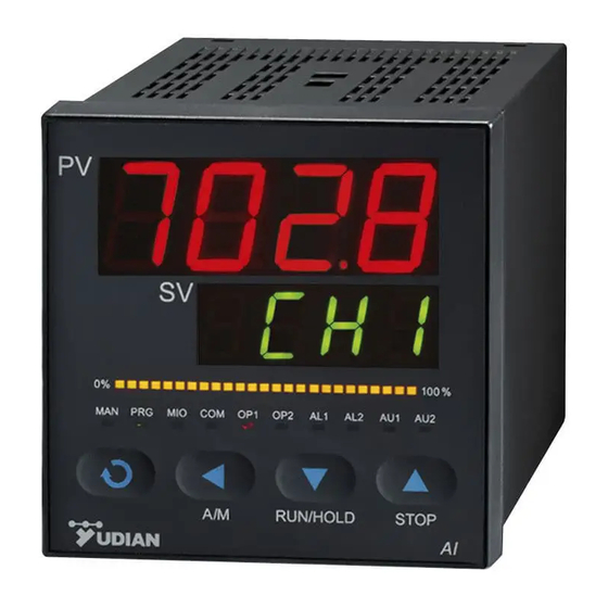
4. DISPLAYS AND OPERATIONS Front Panel Description ① Upper display window, displays parameter code, etc. ② Lower display window, displays SV, parameter value, or alarm ③ Setup key, for accessing parameter table and conforming parameter modification. ④ Data shift key, and auto/manual control switch. -
Page 11: Operation Description
4.2.2 If the lower display window alternately display “HIAL”, “LoAL”, “HdAL” or “LdAL”, it means high limit alarm, low limit alarm, deviation high alarm, and deviation low alarm occurs. The alarm display can also be turned off by setting parameter “cF”. 4.2.3. - Page 12 On the basis of disturbance caused by on-off control, oscillation period, amplitude and waveform are analyzed to calculate optimum control parameters. The auto tuning for AI series instrument will gratify for 90% users. Due to the complexity of the automatic process, parameters calculated by auto tuning are probably not the optimal values on some special occasion (mentioned as follows).
-
Page 13: Program Operation (For Ai-518P Only)
Program operation (for AI-518P only) 4.4.1 Setup program once and release in the display status ①, the instrument will be in the setup program Press the key 、 status. The setpoint of the current program StEP will be displayed. Pressing or c can modify the value. -
Page 14: Parameters And Settings
5. PARAMETERS AND SETTINGS The Full Parameter Table Setting Code Name Description Range Alarm is triggered when PV (Process Value) >HIAL; -1999~ alarm is released when PV<HIAL-dF; HIAL High limit alarm +9999 To disable high limit alarm, set HIAL=9999 units or Every alarm can be defined to control AL1,AL2,AU1,AU2 Alarm triggered when PV<LoAL;... - Page 15 Lag time parameter “t” is a new parameter seconds introduced important parameter for AI artificial intelligence algorithm. AI series instrument can use parameter “t” to do fuzzy calculation, and therefore overshoot and hunting do not easily occurs and the control have the best responsibility at the time.
- Page 16 Input spec. Input spec. Cu50 Pt100 stock 0~75mV 0~80ohm resistor input 0~400ohm resistor input 0~20mV voltage input 0~100mV voltage input 0~60mV voltage input WRe3-WRe25 0~1V voltage input WRe5-WRe26 0.2~1V voltage input Input specification extended input 0~37 1~5V voltage input Code specification radiation type...
- Page 17 OP1 select the control output type: OP1=OP1.A x 1 + OP1.B x 10 OP1.A shows the output type of OUTP. It should be compatible with the module installed in OUTP sockets. OP1.A=0, if output modules such as SSR voltage output, relay contact discrete output, thyristor cross zero trigger output, and TRIAC no-contact discrete output are installed in OUTP.
- Page 18 From right side to left side, the first, second, third and fourth digit of ALP individually indicate the alarm output terminal of HIAL, LoAL, HdAL, and LdAL. 0 shows no output. 1 and 2 are spare for future use. 3,4,5 and 6 respectively indicate alarms outputted to AL1, AL2, AU1 or AU2.
- Page 19 The value of dL will determine the ability of filtering noise. There is one intermediate-value filter system and one second order integral digital filter system in AI series instrument. Intermediate value filter takes intermediate value among three continuous values, while integral filter has the same effect as resistance-capacity integral filter.
-
Page 20: Additional Remarks Of Special Functions
StEP value can not be modified. Loc=808, allowed to set all parameters, program and StEP value. Note: that 808 is the password of all AI series instrument. In application the instrument should be set to other values to protect from modifications of parameters. -
Page 21: Alarm Blocking At The Beginning Of Power On(Cf.b=1)
5.2.2 Single phase contact output (oP1-8) Phase-shifting output is usually realised by TRIAC.but it will has influence on heater, so please make sure of the anti-interference of other equipments when use it. 5.2.3 SV limit setting (only for AI-518,and CF.C=0) SV is usually between HIAL and LoAL. -
Page 22: Widely Used Control Mode
RS232/RS485 changable. One computer with two communication interfaces are workable with 100 units controllers. Diffferent communication addresses are needed. AI-485 AIBUS is advised to be used with AI series instruments. Computer AI series intruments upto 100units 6. -
Page 23: Ai Artificial Intelligent Regulator
4~20mA. 6.3 AI artificial intelligent regulator AI series controllers are developed with advanced AI artificial intelligent fuzzy logic control mode, high accuracy. Advanced Auto turning function can help users to set parameters. AI-518P has the programmable control function. When CtrL is 1-4, then the unit is able to regulate other functions. -
Page 24: Programming And Operation Editting
(cooling-down). This phenomenon is normal. 7.2 Programming and operation editting Programming of AI series instrument has uniform format of temperature-time-temperature, which means that temperature set for current StEP will change to temperature set for next StEP after the time set for the current StEP. - Page 25 jump to StEP5. StEP5: C05=160 , t05=0 The program get in Hold state, and run operation executed by operator is needed for the program to continue running to StEP 6. StEP6: C06=100 , t06=-151 Alarm 1 is switch off, and jump to StEP1 to start from beginning. In this example, it is assumed that the positive deviation alarm is set to 5℃.
- Page 26 AI-518P has the advanced function of flexible program arrangement. Normally, when the program stops, the StEP will be automatically set to1. Thus if StEP is not change to other value, a program will start from step1. If multiple curves are defined, the control can jump to different curve by setting step 1 as jump segment.
Need help?
Do you have a question about the AI Series and is the answer not in the manual?
Questions and answers
I programme my yudian controller to hold for 15mins at 1200°c then I want to stop the programme. How do I do this?
To stop the program on a Yudian AI Series controller after holding for 15 minutes at 1200°C, follow these steps:
1. Set the program step: Define a step with a setpoint of 1200°C and a step time of 15 minutes.
2. Hold for 15 minutes: The controller will maintain 1200°C for the defined time.
3. Stop the program: After the step time expires, set the next step to stop the program.
If the program is already running, you can manually stop it by using the hold or stop function available in the program settings.
This answer is automatically generated