Table of Contents
Advertisement
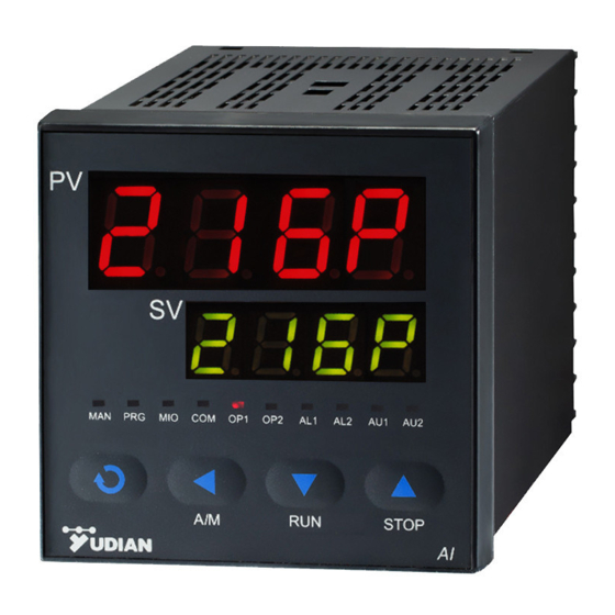
AI-519 ARTIFICIAL INTELLIGENCE INDUSTRIAL CONTROLLER
(Applicable for accurate controls of temperature, pressure, flow, level, humidity etc.)
CONTENTS
1.
SUMMARY ............................................................................................................................................................... 1
1.1
1.2
1.3
1.4
2.
DISPLAYS AND OPERATIONS .......................................................................................................................... 10
2.1
2.2
2.3
2.4
3.
PARAMETERS AND SETTINGS ........................................................................................................................ 12
3.1
3.2
Operation Instruction
)
Yudian (H.K.) Automation Technology Co. Ltd.
Website:
http://www.yudian.us http://www.yudian.com.hk
Tel: +852-2770 8785 Fax: +852-2770 8796
Ver. 8.2
Email:
sales@yudian.com.hk
10
10
11
11
12
13
1
1
4
6
Advertisement
Table of Contents

Related Manuals for Yudian AI-519


Summary of Contents for Yudian AI-519
-
Page 1: Table Of Contents
Yudian (H.K.) Automation Technology Co. Ltd. Website: http://www.yudian.us http://www.yudian.com.hk Email: sales@yudian.com.hk Tel: +852-2770 8785 Fax: +852-2770 8796 AI-519 ARTIFICIAL INTELLIGENCE INDUSTRIAL CONTROLLER Operation Instruction Ver. 8.2 (Applicable for accurate controls of temperature, pressure, flow, level, humidity etc.) CONTENTS SUMMARY ................................1... -
Page 2: Summary
① It implies that the model is AI-519, front panel dimension is 96×96mm, no module installed in MIO (Multi-function I/O) slot, X3 linear current output module installed in OUTP (main output), L5 (dual relay contact output module) in ALM (alarm), no module installed in AUX (auxiliary output), RS485 communication interface with photoelectric isolation is installed. - Page 3 +0.5 +0.5 ×76 front panel 160×80mm(width×height), cut out 152 mm, depth behind mounting surface 100mm. +0.5 +0.5 ×152 front panel 80×160mm(width×height), cut out 76 mm, depth behind mounting surface 100mm. On top of C, there is additional light bar with 50 segments and 2 levels of luminosity. +0.5 +0.5 ×68...
- Page 4 Solid-state relay, SSR voltage output module (DC12VDC/30mA) W1 TRIAC no contact normal open discrete output module (Capacity: 100~240VAC/0.2A, burnt-proof) W2 TRIAC no contact normal closed discrete output module (Capacity: 100~240VAC/0.2A, burnt -proof) RS232 communication interface module, occupying internal 12VDC power. ⑦...
-
Page 5: Technical Specification
can largely decrease the interference spark of the equipment, and greatly improve the stability and reliability of the system. Since the driver element is TRIAC, it is suitable for controlling 100-240VAC (not for DC power) with current up to 80A. For the current larger than 80A, an intermediate relay is needed. - Page 6 AI PID with auto tuning, adopting AI artificial intelligence algorithm. Control Period : 0.5~120.0 seconds selectable at interval of 0.5 seconds Output mode (modularized) Relay contact output (NO+NC, L1 or L4 module): 250VAC/2A or 30VDC/1A TRIAC no contact discrete output (NO or NC): 100~240VAC/0.2A (continuous), 2A (20mS instantaneous, repeat period≥5s) SSR voltage output: 12VDC/30mA (used to drive SSR).
-
Page 7: Rear Terminal Layout And Wiring
1.4 Rear Terminal Layout and Wiring Wiring diagram at back side 1: For linear voltage input, if the range is 100-240VAC~ Thyristor trigger output(K1/K3) below 500mV, connect to terminals 19 and 18. 0~5V or 1~5V signal can be input from terminals 17 and 18. - Page 8 Wiring diagram of D2 size instruments (48×48mm) 1: D2 size instruments don not support native 0~ 5V or 1~5V linear voltage input. The workaround 100-240VAC~ is done by voltage divider into 0~500mV or 100~ Thyristor trigger output(K1) 500mV. External precise resistor 25ohm can be OUTP parallel shunt to convert 4~20mA to 100~500mV then input from terminals 9 and 8.
- Page 9 Wiring diagram of D5 size instruments 1: D5 size instrument are fixed with one channel alarm and communication. 2: Main output can be selected among G, X5, L2, K1, K5, K6 or W1. Wiring diagram of D7 size instruments (22.5 x 100mm) 1: Input 0~5V/1~5V input from 12+, 11- 500mV below input from 10+, 11-...
- Page 10 Wiring diagram of E7 size instruments (22.5 x 100mm) 1: Input 0~5V/1~5V input from 12+, 11- 500mV below input from 10+, 11- 4~20mA with 250ohm shunt resistor converted to 1~5V, input from 12+, 11- 2: Fixed with one channel alarm and communication 3: Main output can be selected among G, X3, L2, K1, K5, K6 or W1.
-
Page 11: Displays And Operations
⑥ Data increase key, and also stop key ⑤ ⑦ LED indicator. PRG indicator is non-applicable for AI-519. The lighting of MAN means in manual output status. MIO, OP1, OP2, AL1, AL2, AU1 and AU2 indicate I/O operation of the corresponding module. -
Page 12: Parameter Setting Flow Chart
Parameter Setting Flow Chart Power On Field Parameters Auto Tuning Process Value High Limit 2 Sec Parameter AT Setpoint Alarm HIAL 2sec Next Parameter 2Sec 2Sec Auto Tuning Output 60% Parameter Lock Password Parameter AT (Auto Mode) incorrect 2sec Password correct Output 60% High Limit (Manual Mode)... -
Page 13: Parameters And Settings
displaying output magnitude, the output magnitude can be modified by pressing . By setting M-A parameter, the instrument can be locked at automatic or manual control mode to avoid entering manual operation by mistake. Auto Tuning (AT) When artificial intelligence PID control or standard PID control is chosen (CtrL=APId or nPId), the PID parameters can for 2 seconds, the “At”... -
Page 14: Complete Parameter Table
3.2 Complete Parameter Table The parameters can be divided to 8 groups including alarm, control, input, output, communication, system, setpoint and field parameter definition. They are listed as below in sequence: Setting Code Name Description Range High limit Alarm on when PV (Process Value) >HIAL; alarm off when PV<HIAL-AHYS HIAL alarm Alarm output action can be defined by parameter AOP. - Page 15 CtI is recommended to be 1/4 – 1/10 of derivative time. (It should be integer times of 0.5 second.) When output type is set to relay (OPt or Aut is set to rELY), CtI will be limited to more than 3 seconds. Auto tuning will automatically set CtI to suitable value considering both control precision and mechanical switch longevity.
- Page 16 and generally is 1/5 to 1/10 of derivative time. 0-20: 0~20mA linear current output. X3 or X5 module should be installed in OUTP slot. 4-20: 4~20mA linear current output. X3 or X5 module should be installed in OUTP slot. PHA: single-phase phase-shift output. K5 module should be installed in OUTP slot. PHA is only for 50Hz power supply, and don’t support bidirectional control system.
- Page 17 Additional Notes Decimal Places When the measuring value and all parameter value shows 0.1℃ or 0.1℉ during measuring temperature (depends on parameter setting Fru), the range of parameter will become –999.0℃~+3000.0℃ or –999.0℉~+3000.0℉, even the default range is-9990~+30000. The decimal place after 999.9 will be truncated. For linear signal definition, the decimal place are only for display.
Need help?
Do you have a question about the AI-519 and is the answer not in the manual?
Questions and answers