
Related Manuals for Yudian AI-8


Summary of Contents for Yudian AI-8
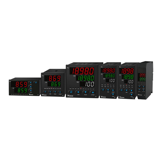
- Page 1 AI-8 Artificial Intelligence High-performance Multi-functional Industrial Regulator User’s Manual (V9.2)...
- Page 2 Scan the code to view the video tutorial www.yudian.com eserved©2022 Technical Support Hotline: 400 888 2776 All Rights R S175-08...
-
Page 3: Table Of Contents
CONTENTS 1. Summary ..............................1 1.1 Main Features ..............................1 1.2 Ordering Code Definition ........................... 5 1.3 Using Modules ..............................10 1.4 Technical Specificatioon ..........................18 1.5 Energy-saving and Environmental Protection Design ..................21 2. Installation and Wiring Method ......................23 2.1 Installation ............................... 23 2.2 Wiring ................................ - Page 4 4.3 Complete Parameter Table ..........................46 5. Common Function Description ......................75 5.1 SCR Trigger Output Function ..........................75 5.2 Position Proportional Output Function ......................78 5.3 External Event Input Function ......................... 80 5.4 Quick Tuning of AAT Function ........................81 5.5 External Given Function ..........................82 5.6 Soft-starting Function ............................
- Page 5 5.18 Nonlinear Power Control Function of High Temperature Furnace ..............95 6. Program Control(Pno≥1) ........................98 6.1 Function and Concept ........................... 100 6.2 Programming ..............................101 7. Display/Alarm Symbols and FAQs ...................... 108 7.1 Display/Alarm Symbols ..........................108 7.2 FAQs ................................112...
-
Page 6: Summary
● High-precision low-temperature drift measurement technology is employed, which also uses 22/24BIT high- resolution A/D converter customized by Yudian as well as 50Hz/60Hz interference suppression function. ● Its power supply of the controller adopts the global switching power supply in the range of 100~240VAC, which provides comprehensive power protection function. - Page 7 ● When the parameter Pno is set to 0, the built-in program control function is fully compatible with the fixed-point operation mode. When it is set to 1, only the given value and timing control time need to be set. AI-8*8 series can...
- Page 8 ● The automatic/manual non-disturbance switching function can be set to be used as a hand-held communicator. ● With external given value control function (only AI-8*8 series) and measured value / given value transmission as 4~20mA or 0~20mA output function. ● With built-in 50-point table/poly-line processing function, which can be used for multi-point correction of measured value input and high-temperature furnace output to follow the measured value limit and other functions.
- Page 9 ⚠ CAUTION This manual introduces the AI-8 series artificial intelligence controller of version V9.2. Some of the functions introduced in thbetween different models and versions of the meter. Be sure to ask the user to read this manual carefully in order to use the instrument correctly and give full play to the function of this instrument. Before using the AI instrument, its input, output specifications and functional requirements should be correctly set to the parameters.is...
-
Page 10: Ordering Code Definition
1.2 Ordering Code Definition 1.2.1 AI-8 Panel-mounted/Rail-mounted Instrument The panel-mounted panel model of the AI-8 series artificial intelligence temperature controller/regulator consists of 9 parts: AI-898 24VDC - F2 - ① ② ③ ④ ⑤ ⑥ ⑦ ⑧ ⑨ This means the instrument: ①the basic model is AI-898; ②the panel size is A type (96×96mm); ③the auxiliary input (MIO) has no module installed;... - Page 11 AI-858 ( level 0.2 accuracy, 5-year free warranty, full-featured artificial intelligence controller/regulator) AI-838 ( level 0.25 accuracy, 3-year free warranty, full-featured artificial intelligence controller/regulator) AI-828 ( level 0.3 accuracy, 2 years free warranty, full-featured artificial intelligence controller/regulator) AI-826 ( level 0.3 accuracy, 2 years free warranty, multifunctional artificial intelligence controller/regulator) Note: Compared with the 8*8 series, the 8*6 series lacks the valve forward/ reverse function and the external given function, and the program segment can be set to 1 segment at most.
- Page 12 ② Indicates instrument panel size specifications Socket Welding Panel Size Module Module Panel type, 96×96mm( W*H), hole size 92×92mm Panel type, 96×96mm (W*H), with light bar Panel type, 96×96mm (W*H), dual 5-digit display with light bar Panel type, 96×96mm (W*H), double-row 5-digit display + third-row 4-digit display Panel type, 160×80mm (W*H), opening size 152×76mm Panel type, 80×160mm (W*H), opening size 76×152mm Panel type, 72×72mm (W*H), hole size 68×68mm...
- Page 13 ⑧ Indicates the power supply of the instrument: if not written, it means using 100~240VAC power supply, 24VDC means using 20-32VDC power supply. ⑨ Indicates the extended scale specification of the instrument (if not, do not write it), AI-8 series has stored the commonly used thermocouple and thermal resistance input specifications (see the technical specifications later for details), but if the specifications other than the above are used Input signal, users are allowed to expand an input specification.
- Page 14 Note 1: This instrument is a maintenance-free instrument that adopts automatic zero adjustment and digital calibration technology. If the measurement is out of tolerance, the problem can be solved by cleaning and drying the inside of the instrument. If drying and cleaning cannot restore the accuracy, this instrument is regarded as a faulty instrument and sent back to the factory for maintenance;...
-
Page 15: Using Modules
1.3.1 Function Definition of Module Socket AI-8*8 series instruments have 5 (MIO\OUTP\ALM\AUX\COMM) optional function module sockets (including 3 for D, D61 panel type and D7 rail type, namely OUTP, AUX and COMM /AL1; D71 rail type can be installed with 4 modules of OUTP, AUX, ALM and COMM);... - Page 16 1.3.2 Models Common Module Name Function Description N(or /) No module installed Large-capacity large-volume relay normally open contact switch output module, module capacity: 30VDC/2A, 250VAC/2A. Small capacity small volume relay normally open + normally closed contact switch output module, module capacity: 30VDC/1A, 250VAC/1A, suitable for alarming. Small capacity small volume relay normally open + normally closed contact switch output module, module capacity: 30VDC/1A, 250VAC/1A, suitable for alarming.
- Page 17 Two-way SCR non-contact and 5V voltage output module, dedicated for valve motor control, capacity: 100~240VAC/0.2A, "not burn out" feature, no welding module Solid state relay driving voltage output module, 12VDC /30mA. Two-way solid state relay drive voltage output module, two-way 12VDC /30mA. K50/K60 One-way 220VAC/380VAC "not-burn-out"...
- Page 18 Photoelectrically isolated RS232C communication/printing interface module (if printing function is required, please specify). V24/V12/ Isolated 24V/12V/10V/5V DC voltage output, available for external transmitters or other circuits, with a V10/U5 maximum current of 50mA. I2/I5 Switch/frequency signal input interface, which can be used for external switch contact or frequency signal input.
- Page 19 1.3.3 Module Installation and Replacement The module can be installed before the instrument is delivered, and the corresponding parameters can be set correctly according to the user's requirements when ordering. If the module is damaged or the function needs to be changed, the user can also replace the module by himself.
- Page 20 instrument. If the user installs the above two modules with isolation function at the same time, the two modules cannot be electrically isolated from each other because they share the power supply of the isolated part. For this purpose, new modules such as S4 (RS485 communication interface) and X5 (linear current output) are designed.
- Page 21 is SCR, thus it is only suitable for controlling the AC power supply of 100-240VAC specification, and cannot be used to control the DC power supply. Since the output terminal is connected in series with a protection device, the maximum continuous control current is 0.2A, and the instantaneous current is allowed to reach 2A.
- Page 22 voltage) can also be used to drive the load if mechanical contacts are not preferred or cannot be installed due to height constraints.
-
Page 23: Technical Specificatioon
1.4 Technical Specifications ● Input specifications (one instrument can be compatible): Thermocouple: K, S, R, E, J, T, B, N, WRe3-WRe25, WRe5-WRe26, etc. Thermal resistance: Cu50, Pt100, Ni120 Linear voltage: 0~5V, 1~5V, 0~1V, 0~100mV, 0~20mV, -5~+5V, -20mV~+20mV, etc. Linear current (requires external shunt resistor or install I44 module): 0~10mA, 0~20mA, 4~20mA, etc. Extended Specifications: On the basis of retaining the above input specifications, users are allowed to customize an additional input specification ●... - Page 24 ● Adjustment method: Position adjustment method (adjustable hysteresis) AI artificial intelligence adjustment, advanced control algorithm including fuzzy logic PID adjustment and parameter self-tuning function Standard PID tuning ● Output specifications (modular): Relay contact switch output (normally open + normally closed): 250VAC/2A or 30VDC/2A SCR non-contact switch output (normally open or normally closed): 100~240VAC/0.2A (continuous);...
- Page 25 ● Isolation withstand voltage: the voltage between power supply terminals, relay contacts and signal terminals is ≥2300V, while the voltage between the isolated weak current signal terminals is ≥600V. ● Power supply: 100~240VAC or DC, -15%, +10% / 50~60Hz; or 24VDC/AC, -15%, +10% ●...
-
Page 26: Energy-Saving And Environmental Protection Design
1005°C (the temperature range is 1000~1010°C) to maintain normal production under different ambient temperature changes. While the temperature drift of AI-8 series instruments can be reduced to within ±0.3~1°C. In this case, setting the temperature at 1001°C (temperature range of 1000~1002°C) can stabilize production, so that the average temperature of the kiln can be reduced by 3 ~4°C, and the lower the average temperature of an industrial furnace, the... -
Page 27: Installation And Wiring Method
2. Installation and Wiring Method 2.1Installation 2.1.1Panel Mounting Method The distance between the installation holes of the instrument should be set at an appropriate distance according to different sizes and installation brackets. If necessary, the instruments can be installed side by side closely. -
Page 28: Wiring
2.1.2 Installation Method of DIN-rail Module ① Install the module on the 35mm DIN rail. ② The rail module must be installed vertically, and the recommended distance is at least 50mm. ③ When wiring the terminals, please set the tightening torque to 0.39 ~ 0.58N·m. - Page 29 2.2.2 Panel Mounted Instrument Wiring Diagram Note: Due to technical upgrades or special orders, etc., if the random wiring diagram of the instrument is inconsistent with this manual, please refer to the random wiring diagram. The E5/E51 rail wiring is the same as the panel mounted instrument.
- Page 30 ③ Thermocouples with different graduation numbers use different compensation wires for thermocouples. When using the internal automatic compensation mode, the compensation wires should be directly connected to the terminals on the back cover of the instrument, and cannot be converted into ordinary wires in the middle, otherwise measurement errors will occur.
- Page 31 ■ The wiring diagram of D-type panel instrument (72mmX72mm) is as follows: Note 1: The linear voltage range of 0~100mV and below is input from the 13+ and 12- terminals, and the voltage signal of 0~1V and above is input from the 11+ and 12- terminals. Note 2: 4~20mA linear current input can be changed into 1~5V voltage signal with 250Ω...
- Page 32 ■ The wiring diagram of D61 panel instrument (48X48mm) is as follows: Note 1: D61 panel meter does not support direct input of linear voltages of 0-1V and above. If necessary, an external precision resistor should be used to divide the voltage and the signal should be converted to 0~100mV input;...
- Page 33 2.2.3 DIN Rail Module Wiring Diagram ■ The wiring diagram of D71 panel instrument (22.5X100mm) is as follows: Note 1: 0~1V and above voltage signals are input from 16+, 15-, 0~100mV and below signals are input from 14+, 15-; 4- 20mA linear current input and 250 ohm resistor into 1-5V, then input from 16+, 15-.
- Page 34 2.2.4Thermocouple Cold Junction Compensation Method Description Using the wiring method to select the thermocouple cold junction automatic compensation mode: When a thermocouple is used as the input signal, according to the principle of thermocouple temperature measurement, it is necessary to perform temperature compensation on the cold end of the thermocouple. The AI instrument can measure the temperature near the rear terminal of the meter and automatically compensate the cold end of the thermocouple.
-
Page 36: Display And Operation
3.Display and Operation 3.1 Panel Description ①The upper display window displays the measured value PV, parameter name, etc. ② The middle display window displays the given value SV, alarm code, parameter value, etc. ③The lower display window displays the output percentage MV ④Setting key, used to enter parameter setting state, confirm parameter modification, etc. -
Page 37: Parameter Setting Process
3.2 Parameter Setting Process... -
Page 38: Procedure Setting Process
3.3 Procedure Setting Process... -
Page 39: Operating Instructions
25 seconds. 3.4.2 Quick Operating Instructions All functions of the AI-8 series can be completed by modifying parameters, but for some commonly used functions, such as modifying the given value and running/stopping the program, we have designed shortcut operations to simplify the use. - Page 40 "run" symbol. AI-8 series will start the program operation in the stopped state. For AI-8 series and the parameter PAF.F=1, if the program of the instrument is already in the running state, the operation will enter the hold running (HoLd) state, and the time will be paused in this state, and the run operation will be executed again.
- Page 41 and decrease the manual output value. By setting the A-M parameters, the instrument can also be fixed in the automatic state and not allowed to be switched to the manual state by the operation of the panel keys, so as to prevent entering the manual state by mistake.
- Page 42 OPL and OPH. In some occasions where the output is not allowed to change greatly, such as where some actuators use control valves, conventional self-tuning is not suitable. In this regard, AI-8 series instruments have manual self-tuning mode. The method is to adjust manually first, and after the manual adjustment is...
- Page 43 process. Depending on the system, the time required for auto-tuning can vary from seconds to hours. Note 3: The control hysteresis parameter CHYS also affects the auto-tuning results. Generally, the smaller the setting value of CHYS, the higher the accuracy of the auto-tuning parameters. However, if the CHYS value is too small, it may cause the misoperation of the bit adjustment due to the input fluctuation, which may set completely wrong parameters.
- Page 44 3.4.3 Instructions for E5 Rail Mounted Instruments AI-8 E5 rail-mounted instrument itself has no display and keyboard. It can install an RS485 communication interface, and use the connection with the upper computer or touch screen to complete the function and operation of its display interface, or use an external E85 keyboard and monitor for display and parameter setting.
-
Page 45: Parameter Description
4.Parameter Description 4.1Typical Setting Process and Common Parameters Please refer to the complete parameter table for the description of the parameters in the figure. For other functions, please refer to the description of common functions. The input range does not need to be set when the thermocouple or thermal resistance is selected for the input specification, and the range is set only when the analog signal input or the transmission function is... -
Page 46: Parameter Lock And Custom Parameter Table
4.2 Parameter Lock and Custom Parameter Table 4.2.1 Parameter Lock(Loc) Loc can provide a variety of different parameter operation authority and password input operation to enter the complete parameter table, and its functions are as follows: Loc=0, allowed to modify the field parameters, and allowed to directly modify the given value in the basic display state;... - Page 47 4.2.2 Custom Parameter Table The parameter table of AI-8 can be programmed to define the function, which means the parameter table of the instrument can be customized for you. In order to protect important parameters from being arbitrarily modified, we call the parameters that need to be displayed or modified in the field as field parameters.
-
Page 48: Complete Parameter Table
4.3 Complete Parameter Table The complete parameter table is divided into 8 blocks, including alarm, adjustment control, input, output, communication, system function, given value/program and field parameter definition, etc. The parameters are as follows: Parm. Meaning Description Range Postal The Addr parameter defines the instrument communication address and has a 0~99 address valid range of 0-80. - Page 49 bAud Baud rate The bAud parameter defines the communication baud rate, ranging from 0 to 28800bit/s (28.8K); When COM location is not used for communication function, bAud COM port can be used as other function by bAud parameter setting: bAud=0, COMM slot transmitted as a set value of 0-20ma for output; bAud=1, as an external switching value input, has the same function as the MIO position.
- Page 50 communic Select communication mode, its calculation method is as follow: 0~255 ation AFC=A*1+D*8+G*64 mode A=0, standard MODBUS; A=1, AIBUS; A=2, MODBUS compatible mode; A=4, compatible with S6 module. D=0, no calibration; D=1, even calibration. G=0, AUX used normally; G=1, AUX used as event input. Note: AFC supports 03H (read parameters and data) and 06H (write a single parameter) under MODBUS.
- Page 51 Enter InP is used to select the input specification, and the input specification 0~106 specificati corresponding to its value is as follows: I nP on code 21 Pt100 22 Pt100(-80.00~+300.00℃) 25 0~75mV voltage input 26 0~100Ω resistance input 27 0~400Ω resistance input 28 0~20mV voltage input 30 0~60mV voltage input 31 0~1V voltage input...
- Page 52 Alarm The 4-digit ones, tens, hundreds and thousands of AOP are used to define the 0~4444 output output positions of 4 alarms such as HIAL, LoAL, HdAL and LdAL, as follows: definition AOP = LdAL HdAL LoAL HIAL The value range is 0-4, 0 means that the alarm is not output from any port, 1, 2, 3, 4 means that the alarm is output by AL1, AL2, AU1, and AU2, respectively.
- Page 53 SPSL parameters, then fully open the valve to memorize the valve feedback signal in the SPSH parameters, and then automatically return to the FEd control mode. Note: AI-8* 6 series doesn’t possess position proportional control output...
- Page 54 Auto OFF, the auto tuning At function is off. on, start PID and Ctl parameter auto-tuning function, and automatically return to tuning FOFF after auto-tuning. FOFF, the auto-tuning function is closed, and it is prohibited to start the auto- tuning from the panel operation. AAt, fast auto-tuning function, automatically returns to OFF after auto-tuning.
- Page 55 Automatic MAn: manually controls the state, and the operator manually adjusts the output of /manual OUTP. control Auto: automatically control status, OUTP output is determined by CtrL after selection calculation. FSv: is compatible with the manual automatic function instrument mode, and it is prohibited to enter the manual automatic switching interface.
- Page 56 It is used to define the number of effective program segments, which can reduce Numbers 0~50 the number of unnecessary program segments as needed, so that the operation and program settings are convenient for the end user. When Pno=0 is set, the program instrument is in constant temperature mode;...
- Page 57 Event The Et parameter has been extended to 2 inputs (modules such as I5 need to be 0-77 Input installed if dual inputs are used), Et=Et1 * 10+Et2, where Et1 and Et2 represent Type event input 1 and input 2, respectively. The numerical meanings of Et1 or Et2 are as follows: 0(nonE): Disable event input function.
- Page 58 Note: If Et1=Et2 is set, the system will execute Et1 first and then Et2, and the result will be based on Et2. CtrL Control OnoF, which adopts position adjustment (ON-OFF), is only suitable for control in mode low requirements. CtrL APID, an advanced AI artificial intelligence PID adjustment algorithm, is recommended.
- Page 59 When it is set to 0~100%, it is used as the minimum limit value of regulating Output -110~ output OUTP in normal one-way regulation. lower limit +110% When the setting is - 1~- 110%, the instrument becomes a two-way output system with heating/cooling dual output function.
- Page 60 Cooling The AUX output type is defined only when AUX is used as an auxiliary output in output the heating/cooling two-way regulation. type SSr, output SSR driving voltage or SCR zero crossing trigger time proportional signal, install G or K1 modules respectively, and adjust the output power by adjusting the on-off time ratio, with a period of 0.5-4.0 seconds.
- Page 61 CHYS Control It is used to avoid frequent action of ON-OFF position regulating output relay. 0~9999u return It is used to avoid frequent action of ON-OFF position regulating output relay. CHYS difference When it is used for reaction (heating) control, the relay is turned off when PV is (dead greater than SV, and the output is switched on again when PV is less than SV- zone,...
- Page 62 Proportion Define the proportional band adjusted by APID and PID, and the unit is the same 1~32000 al band as the PV value, rather than the percentage of the range. unit Note: The At function is usually used to determine P, I, D and Ctl parameter values, but for familiar systems, such as batch-produced heating equipment, the known correct P, I, D, Ctl parameter values can be directly entered.
- Page 63 Control When SSR, thyristor or current output is used, it is generally set to 0.5-3.0 0.2~300. cycle seconds. When relay switch is used for output or heating/cooling dual output control system is used for output, short control cycle will shorten the service life of mechanical switch or lead to frequent switching and starting of cold/hot output.
- Page 64 Cold output Define the integral time of cold output adjusted by PID, in seconds, and the 0~9999s integration integral action is canceled when I=0. time Cold Define the differential time of cold output adjusted by PID, in 0.1 seconds. When output d=0, the differential action is canceled.
- Page 65 The Scb parameter is used for translation correction of input to compensate the Input -9990~ error of sensor, input signal, or thermocouple cold end automatic compensation. translation +4000 Note: Generally, it should be set to 0. Incorrect setting will lead to measurement correction unit error.
- Page 66 50C means that the power frequency is 50Hz, and the input has the maximum Power anti-interference capability to this frequency; The unit of temperature is ℃. frequency 50F means that the power frequency is 50Hz, and the input has the maximum temperatu- anti-interference capability to this frequency;...
- Page 67 Advanced AF parameter is used to select advanced functions, and its calculation method is 0~255 function as follows: code AF=A×1+B×2 +C×4 +D×8+E×16+F×32+G×64+H×128 A=0, HdAL and LdAL are deviation alarms; A=1, HdAL and LdAL are absolute value alarms, so the instrument can have two absolute value upper limit alarms and absolute value lower limit alarms respectively.
- Page 68 If G=0, the upper limit alarm is allowed when the measured value increases due to sensor disconnection (the upper limit alarm setting value should be less than the upper limit of signal range); G=1, the increase of measured value caused by sensor disconnection does not allow upper limit alarm.
- Page 69 H=1, the CT function is activated and needs to work with I9 module to detect current, which can be used for judging load disconnection or actuator short circuit. Note: The AI-8 * 6 series does not support external functions. PAF parameter is used to select program control function, and its calculation Program...
- Page 70 B=0, slope mode, when there is temperature difference during program operation, different temperature rise modes can be defined according to broken line transition, and it can also be used for cooling operation; B=1, platform mode (constant temperature mode), each segment of the program defines the given value and holding time, reaching the conditions of the next segment can be limited by the rdy function, and the rising/cooling rate can be limited by the SPr/SPrL parameter;...
- Page 71 at the temperature rise rate limit defined by SPr. The PRG light will flash under the ℃/ min ure-rising temperature rise rate limit state. rate limit SPR is valid for fixed point control (Pno=0) and program platform mode, but not for slope mode.
- Page 72 When the instrument control mode is PID or APID, Ero defines the output value to Output -110 be adjusted when the input is over range (usually caused by sensor failure or value at ~110% disconnection). excessive AF2 parameter can define whether the Ero is valid and the setting mode. When range the Ero is defined as the automatic setting mode and the deviation is less than 4 measurement units, the instrument automatically stores the integral output value, so...
- Page 73 HIAL Upper When the measured value PV is greater than the HIAL value, the instrument will -9990~ limit alarm generate an upper limit alarm; When the measured value PV is less than the HIAL- H I AL +32000 AHYS value, the instrument will remove the upper limit alarm. unit Note: Each alarm can be freely defined as controlling the action of output ports such as AL1, AL2, AU1 and AU2, or not doing any action.
- Page 74 AHYS Alarm Also known as alarm dead zone, hysteresis, etc., it is used to prevent the alarm 0~2000 return critical position from frequently acting due to the alarm relay. Please refer to the unit AHYS difference above. AdIS Alarm OFF, the alarm symbol is not displayed at the lower display during alarm. indication On, in case of alarm, the alarm symbol is alternately displayed on the lower Ad I S...
- Page 75 When the switch is off, SV=SP1, and when the switch is on, SV=SP2. PASd Password When PASd is equal to 0-255 or AF.D=0, set Loc=808 to enter the complete 0~9999 parameter table. PASd When PASd is equal to 256-9999 and AF.D=1, Loc=PASd must be set to enter the parameter list.
- Page 76 Nonc N.O. /N.C. A single channel alarm relay can simultaneously output normally open and 0~15 selection normally closed, while a dual channel alarm module L3 only has normally open nonc output. However, the normally open output can be defined as normally closed output through the non c parameter.
- Page 77 EFP1 Lower The percentage is used by EFP1~3. The CT function (AF2. H=1) needs to be 0~100 limit of enabled, paired with the I9 module, and the external transformer needs to be EFP1 current converted to AC 0~50mA. Try to match two or more transformers, so that the alarm normal current percentage is around 20%~40%.
- Page 78 E=0, AUX slot is in normal use; E=1, AUX slot for transmission output, needs to be paired with AUX. F=0, AUX for transmission output and transmits PV; F=1, AUX for transmitting output and transmits SV. Note: AI-8 * 6 series does not have EAF function...
- Page 79 Therefore, when the instrument is in the STOP status, the command to switch the program is executed. Note: AI-8 * 6 series does not have Prn function Definition One to eight field parameters can be defined, which are commonly used after Loc EP1- locking and need to be modified by field operators.
-
Page 80: Common Function Description
5. Common Function Description Note: For a complete description of the parameters involved in the following function introduction, please refer to the complete parameter table. 5.1 SCR Trigger Output Function 5.1.1 Single-phase Phase-shift Trigger Output Parm. Setting Description SCR single-phase phase-shift trigger output, SCR is 5-500A, if a larger-size SCR will be used, please specify when ordering. - Page 81 Note 1: Resistor-capacitor absorption and varistor must be added when phase-shift trigger is used to improve possible harmonic interference. Note 2: It is recommended to use a SCR power module. One power module contains two unidirectional SCRs, as shown by the dotted line in the figure. Note 3: When using the K60 module, the load power supply is 380VAC;...
- Page 82 5.1.2 Single-phase/Three-phase Zero-crossing Trigger Output Parm. Setting Description SCR single-phase/three-phase zero-cross trigger output, SCR is 5-500A, if a larger-size SCR will be used, please specify when ordering. The output power is adjusted by adjusting the ON-OFF time ratio, and the cycle is usually 0.5-4.0 seconds. Select the appropriate varistor according to the load voltage to protect the SCR, the output wiring of the K1 module is the same as the single-phase phase-shift trigger output, and the three-phase zero-crossing wiring is shown in the following figure:...
- Page 83 K3 three-phase three-wire fully controlled K3 three-phase three-wire star and power module star and delta wiring diagram delta wiring diagram (TRIAC) (single-phase SCR anti-parallel)
-
Page 84: Position Proportional Output Function
5.2.Position Proportional Output Function 5.2.1 Proportional output with feedback position After setting this output, if OPH is less than 100, the instrument will automatically set the valve position when powered on, that is, it will automatically close the valve when powered on, and the time is the valve stroke time.The OPH parameter can limit the maximum valve opening when the measured value PV is less than the parameter OEF. - Page 85 5.2.2 Proportional output with feedback position When there is proportional output with feedback position, it is necessary to do valve position auto-tuning. The instrument will automatically close the valve first, and then fully open the valve, then measure the feedback signal to set the valve position and save it.
- Page 86 Parm. Setting Description FEd/FEAt After other parameters are set and wiring is completed, set the instrument to FEAt to FEAt open the valve position auto-tuning SPSL It is the lower limit of the valve position, which is automatically written after the valve SPSL position is set SPSH...
-
Page 87: External Event Input Function
5.3 External Event Input Function If I2 module is installed on MIO socket (or set bAud=1, and I2/I5 module is installed on COMM socket), a switch can be connected externally, and control functions can be executed through on-off of the switch to realize operation stop switching, dual set value switching, manual/automatic switching, etc. -
Page 88: Quick Tuning Of Aat Function
5.4 Quick Tuning of AAT Function Traditional periodic oscillation auto-tuning requires 2 cycles to set PID parameters, which requires a long debugging time. The fast tuning function is that when the instrument is powered on and in the full power heating output state, the PID parameters can be calculated by analyzing the temperature rise curve, and the PID parameters can be set in advance without periodic oscillation. -
Page 89: External Given Function
5.5 External Given Function External setting refers to changing the setting value of the instrument through external analog signals, which can realize the functions of proportional adjustment, cascade adjustment, manual operator, etc. The external given signal is fixed as 0-5/1-5V voltage signal. When the external given function is valid, the internal given value does not work. When the external given signal is disconnected, the internal given value will be switched automatically. -
Page 90: Soft-Starting Function
5.6 Soft-starting Function This function can be enabled when the equipment needs to gradually increase output according to time when it is powered on or started up for operation. If the measured value PV is less than OEF when the instrument is powered on or stopped, the maximum allowable output of the main output OUTP after operation will rise to the output percentage set by OPH after the set time. -
Page 91: Heating And Cooling Dual Output Function
5.7 Heating and Cooling Dual output function When the OPL parameter is set to - 1~- 110% and the control mode Ctrl is set to APId/nPid, the instrument will become a two-way output system, with two opposite PID control outputs, the main output OUTP and the auxiliary output AUX. -
Page 92: Overrange Output Definition Function
5.8 Overrange Output Definition Function During the operation of the instrument, when the input sensor signal exceeds the range or "orAL" alarm occurs abnormally, the instrument will automatically close the output. In some special occasions, dangerous situations may occur, for example, the control instrument of the cooling water valve in the machine room closes its output due to abnormal measurement signals, which may cause overheating or burning of the equipment. -
Page 93: Limiting Function Of Temperature Rise/Fall Rate
5.9 Limiting function of Temperature Rise/Fall Rate When the equipment does not allow rapid heating or cooling due to material and other factors, the function of setting the temperature rise/drop rate limit is effective. After the instrument changes the set value or the program starts (platform mode), if the measured value is not equal to the set value, it will rise/fall to the set value or program segment value according to the set rise/fall rate limit value. -
Page 94: Power-On Operation Mode Selection Function
5.10 Power-on Operation Mode Selection Function After the equipment is powered on or powered on again due to accidental power failure, the instrument can select the power on operation mode to change the working state of the instrument as required. Parm. -
Page 95: Exempt From Alarm Function At Power-On
5.12 Exempt from Alarm Function at Power-on The instrument often leads to some unnecessary alarms after it is just powered on, for example, when the electric furnace temperature is controlled (heating control), and it is just powered on, its actual temperature is far lower than the given temperature. -
Page 96: Communication Function
5.13 Communication Function AI series instruments can be installed with S or S4 and other communication modules at the COMM position, and can be connected with computers to realize various operations and functions of the instrument. For the computer without RS485 interface, one RS232C/RS485 converter or USB/RS485 converter can be added. Each communication port can directly connect 1-60 instruments. -
Page 97: Temperature Transmitter/Programmed Generator
(PV) or the given value (SV) from the OUTP or COMM terminal. When the output is defined as current output, AI-8 can be used as a temperature transmitter, and when the program function is enabled, it can be used as a program given generator. - Page 98 For example, the instrument is required to have the K index thermocouple transmitting function, the temperature range is 0~400 ℃, and the output is 4~20mA. The parameters are set as follows: InP=0, SCL=0.0, SCH=400.0, OPt=4- 20, OPL=0, OPH=100. For the defined transmitter, when the temperature is less than or equal to 0 ℃, the output of X3 or X5 linear current module installed at the OUTP position is 4mA;...
-
Page 99: Fine Control
5.15 Fine Control Fine control refers to that the PID operation resolution is 10 times higher than the display resolution. For example, the instrument temperature signal is displayed as 1 ℃, but the internal PID is still calculated and controlled according to the resolution of 0.1 ℃, which can achieve a much higher control accuracy than the display resolution. -
Page 100: Custom Input Specifications
5.16 Custom Input Specifications When the parameter InP=10 is set, the instrument input specification is a user-defined input type, and non-linear tables can be edited. Setting method: Set Loc parameter to 3698 to enter the table setting state. The parameter A 00 definition table is used for: 0 for input nonlinear measurement or multi segment linear correction of input signal, 1 for nonlinear power control of high temperature furnace;... - Page 101 input, A02=1×25000/5=5000 can be set. K is the signal coefficient, where the coefficient is 20000 when A01. A is 0, 25000 when A01. A is 2, 4 and 10, and 30000 when A01. A is 1. A 03: Define the input signal range, equal to the signal range × K/range, for example, in 1-5V input, if the range is 5-1V=4V, A03=4×...
-
Page 102: Multi-Segment Linear Correction Function Of Input Signal
5.17 Multi-segment Linear Correction Function of Input Signal When the input specification InP is set to plus 64, the instrument has the input multi segment linear correction function. Setting method: Set Loc parameter to 3698 to enter the table setting state (if Loc=808, set Loc to 0 first, exit the parameter setting state, and then enter the parameter state again to set Loc to 3698). -
Page 103: Nonlinear Power Control Function Of High Temperature Furnace
Note: The corrected value is the value of each point, and the point-to-point transition is automatic and linear. When this function is enabled, the instrument can only be displayed within the temperature range set by the table. When the actual temperature exceeds the table range, the instrument will display the orAL overrun alarm. 5.18 Nonlinear Power Control Function of High Temperature Furnace For high-temperature furnaces with non-linear load, the resistance will change dramatically with the temperature change. - Page 104 low temperature zone, but also automatically corrects the parameters of the proportional band at different temperatures. The power limit and the change of the proportional band are both continuous broken line mode, which is better than the grouping mode. The power limit only reduces the actual output of the instrument proportionally, while the display range of the instrument output is still 0~100%.
-
Page 105: Program Control(Pno≥1
6. Program Control(Pno≥1) The AI-8 * 8 program type instrument is used in situations where it is necessary to automatically change the set value for control according to a certain time rule. It not only has the function of 50 segments programming, which can set the rise and fall slope of any given value, but also has programmable/operable commands such as jump, run, pause and stop, which can modify the program during program control operation;... - Page 106 Run (run/HoLd): When the program is in the running state, the time is timed, and the given value changes according to the prearranged program curve. When the running state is maintained (paused), the time stops timing and the given value remains unchanged. The pause operation (HoLd) can be programmed in the program segment. Stop: The execution of stop operation will stop the program running.
- Page 107 75 minutes, so that the program will start running directly from the position of 100 ℃. Curve fitting: it is a control technology adopted by AI-8 instrument. Because the control object usually has the characteristics of time lag, the instrument automatically smooths the linear rise, drop and constant temperature curves...
-
Page 108: Programming
The greater t is, the greater the degree of smoothness is, and vice versa. The smaller the lag time (such as thermal inertia) of the control object, the better the program control effect. Processing program curves by curve fitting can avoid overshoot. - Page 109 segment SP 3=400.0 t 3=120.0; Cool down to SP 4, the cooling time is 120 minutes, and the cooling slope is 2 ℃/minute segment SP 4=160.0 t 4=0.0; When the temperature drops to 160 ℃, it will enter the pause state, and the next section can continue after run is executed segment SP 5=160.0 t 5=- 1.0;...
- Page 110 The advantage of using temperature-time programming method is that the slope setting range of temperature rise and drop is very wide. The heating and constant temperature sections have a unified setting format, which is convenient for learning. Besides, it is more flexible to set curve, and possible to set a continuous heating section (for example, use a heating section with different slopes to approximate functional heating), or a continuous constant temperature section as well.
- Page 111 6.2.2 Platform Mode When parameter PAF.B=1 is set, the platform mode can be selected, which is suitable for applications that do not need to set the temperature rise slope independently and do not need to set the temperature drop slope. It can simplify programming and make more effective use of the number of segments.
- Page 112 The platform mode only needs to set the temperature and constant temperature time. It does not need to set the temperature rise process. As shown in the figure above, the platform mode can be set to skip, stop, cycle, etc. The above settings are actually listed as stop.
- Page 113 6.2.3 Set Program Given Value and Time Each program section includes a given value and time. The range of values that can be set for a given value is limited by SPL and SPH. It is - 999~+3200 ℃, representing the temperature value (℃) to be controlled or the linear definition unit.
- Page 114 For example, if t - 5=- 1.1 is set, it means that when the fifth segment of program is run, AL1 acts, and AL2 releases and jumps to the first segment. For another example, if t - 6=- 0.3 is set, it means that when the sixth segment of program is run, AL1 and AL2 act and continue running the next segment of program (the seventh segment).
- Page 115 6.2.4The Programming Method of Running Multiple Curves The programming method of AI-8x8 is advanced and flexible, and the newly added Prn is used to select numbers (0-9) for the current program group; When the Prn value is modified and the instrument is in the STOP status, the instrument will automatically save the previous 50 program segments to FLASH memory and load a new numbered program segment.
-
Page 116: Display/Alarm Symbols And Faqs
7. Display/Alarm Symbols and FAQs 7.1 Display/Alarm Symbols After the instrument is powered on, it enters the basic display state. At this time, the upper and lower display windows of the instrument display the measured value (PV) and the set value (SV) respectively. The SV display window can also alternately display symbols or display symbols to indicate the status, as shown in the following table: Parm. - Page 117 Press for two seconds to run the instrument. If it fails to run, HoLd Indicates that the instrument please check whether there are functions such as communication and HoLd program function is suspended program segment settings that restrict the running operation. Indicates that the instrument After waiting for the measurement signal to meet the setting program function is in a ready...
- Page 118 When the measured value PV is less than the HIAL-AHYS value, the HIAL Indicates that an upper limit alarm alarm will be automatically canceled, or modify the HIAL to 32000 to has occurred cancel the alarm When the measured value PV is greater than LoAL+AHYS, the alarm LoAL Indicates that a lower limit alarm will be canceled automatically, or modify LoAL to -9990 to cancel the...
-
Page 119: Faqs
When a current upper or lower limit alarm is generated after pairing CtAL current alarm warning with the I9 module, please check the load circuit. Set EFP1 and EFP2 to CtAL 0 to cancel this function Note: If necessary, turn off the character flashing function during upper, lower limit and deviation alarms to avoid excessive flashing (set the ADIS parameter to oFF). - Page 120 that the output state of the instrument is normal. At this time, the multi-meter can be used to detect whether the output terminal signal of the instrument is normal. If the output signal is normal but the back-end actuator does not work. It is necessary to check other equipment or line faults along the output line.
- Page 121 7.2.7 How to set bidirectional output for heating and cooling? Enter the internal parameter table to find the OPL parameter (output lower limit), change the OPL to -1%~-110%, the instrument becomes a bidirectional PID output system, the main output OUTP is used for heating control, and the auxiliary output AUX is used for refrigeration control.
Need help?
Do you have a question about the AI-8 and is the answer not in the manual?
Questions and answers