Advertisement
Quick Links
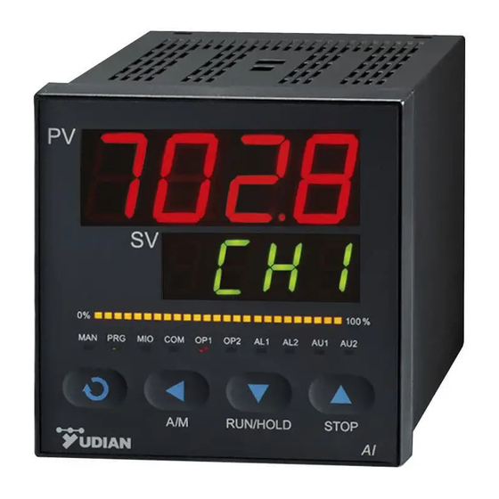
AI-SERIES MULTI-CHANNEL PID TEMPERATURE CONTROLLER
1.
SUMMARY
Multi-channel temperature controller provides thermocouple inputs and solid-state SSR outputs.
Each channel can be set as different type of inputs and works independently. This controller can
either used independently or used with computer or PLC (Programmable Logic Controller). The
supply power can be ordered as 24VDC/AC or 100~240VAC. It complies with ISO9001 quality
assurance. It is highly reliable with EMC standard compatible. The power and all I/O terminals has
passed 4KV/5KHz EFT test. It is able to be stably working under strong interference. By adopting
YUDIAN's new technology, the anti-interference power of multi-channel inputs is as strong as that of
single channel measurement.
● Providing up to 4 channels of programmable inputs, supporting multiple thermocouple inputs, K,
S, E, J, B, N, T, WRe5-WRe25 and etc, with automatic cold junction compensation and linear
voltage (mV) inputs with user defined scale. Individual digital filtering for each channel are
possible to be adjusted or disabled.
● High performance hardware design, which greatly decreased temperature drift and the
interference among the 4 channels. Therefore, this multi-channel controller obtains the same
measurement accuracy and anti-interference ability as that of single channel controller.
● Rail mounted panel with code D5/E5/D7/E7 are available. Those panels without display can be
programmed by connecting the external handset display E8.
● Apart from rail mounted panel D5, every channel has independent high/low limit alarm or
deviation alarm outputs. Those alarms can be assigned to different alarm output slot (AL1 or
AL2) by programming. Alarms from different channels can be assigned to the same alarm slot or
different alarm slots.
● There are 12 programmable Field Parameters. Users can tailor-made the parameter table.
● Advanced communication functions, compatible with the communication protocol of other AI
series instruments such as AI-708 high precision artificial intelligent regulator/temperature
controller. One unit of AI-7048 in communication works as if there are 4 individual units of AI-708
controllers working.
● Among this multi-channel controller series, AI-70482 provides 4 channels of individual inputs
with weak electronic signal isolation among channels. It is suitable for application of grounded
thermocouples of which the negative pole of thermocouple is connected to the probe shell.
AI-7028 / AI-7048
Operation Instruction
Ver. 7.8
1
Advertisement

Subscribe to Our Youtube Channel
Related Manuals for Yudian AI Series


Summary of Contents for Yudian AI Series
- Page 1 It is highly reliable with EMC standard compatible. The power and all I/O terminals has passed 4KV/5KHz EFT test. It is able to be stably working under strong interference. By adopting YUDIAN’s new technology, the anti-interference power of multi-channel inputs is as strong as that of single channel measurement.
- Page 2 ● AI-7048 is fully compatible to AI-7028. AI-7028 is a 2 channel individual controller. The wire connection method is taken reference to the first 2 channel of AI-7048. 2. Technical Specification Input type: Thermocouple: K, S, R, E, J, T, B, N, WRe5-WRe26 Linear voltage: 0~20mV, 0~60mV, 0~100mV, 0~1V, etc.
- Page 3 Wiring diagram of AI-70482 multi-channel temperature controller This wiring diagram is valid for panel size code A, C, E, E5 or etc. For instruments with dimension B and F, the diagram is clock-wisely rotated by 90°. The terminal numbers keep unchanged.
- Page 4 D7 multi-channel temperature controller Wiring diagram Power Base Terminals Terminal 1~2: Power 100~240VAC or 24VAC/DC Terminal 4~5: RS485 communication. Instrument Terminals Terminal 5~8: Positive poles of 4 SSR voltage outputs Terminal 9~10: Positive poles of AL1 and SSR alarm outputs. Terminal 11~12: Negative poles of AL1 and SSR alarm outputs.
-
Page 5: Displays And Operations
DISPLAYS AND OPERATIONS ① Upper display window, displays parameter code, etc. ② Lower display window, displays parameter value, channel no. or alarm code. ③ Setup key, for accessing parameter table and conforming parameter modification. ④ Data shift key, or for switching the channel display in manual/auto. - Page 6 4. MODE indication light: When the instrument is communicating with the host computer, the light will keep flashing in random speed. When the instrument hasn’t received signal from the host computer more than 6 seconds, the indication light should flicker with the same light on time and light off time. It means: The on-off period is as long as 1.6 second means no communication and no alarm (it can be treated as normal);...
- Page 7 5. Setting Parameters: (Note: x means channel number. It can be 1~4.) Parameter Name Remarks Setting range When COMM module interface is used for communication, bAud defines the bAud Baud rate 0 ~ 19.2K bit/S baud rate range is 300~19200bit/s. Every instrument in the same communication line should be assigned to different communication address.
- Page 8 x channel high alarm is triggered when PVx (the present value of x H.ALx Alarm high limit channel)>H.ALx; alarm releases when PVx<H.ALx - HYSx. -999~+3200 ℃ x channel low alarm is triggered when PVx<L.ALx; L.ALx Alarm low limit alarm releases when PVx>L.ALx+HYSx. HYS is set to avoid high frequent alarm on/off actions caused by process HYSx Hysteresis...
- Page 9 need to be modified by field operators, the parameter EP can be set as : EP1=SP1, EP2=SP2, EP3=SP3, EP4=SP4, EP5=none, Loc=0 Then only parameter SP1~4 can be displayed and modified, but via communication, on the host computer, all parameters can be displayed and modified.
Need help?
Do you have a question about the AI Series and is the answer not in the manual?
Questions and answers