Table of Contents
Advertisement
Yudian (H.K.) Automation Technology Co. Ltd.
Website:
http://www.yudian.us http://www.yudian.com.hk
Email:
sales@yudian.com.hk
Tel: +852-2770 8785 Fax: +852-2770 8796
AI-518/AI-518P
ARTIFICIAL INTELLIGENCE INDUSTRIAL CONTROLLER
Operation Instruction
Ver. 7.1
(Applicable for accurate controls of
Temperature, Pressure, Flow, Level and Humidity etc.)
Advertisement
Table of Contents

Related Manuals for Yudian AI-518


Summary of Contents for Yudian AI-518
- Page 1 Yudian (H.K.) Automation Technology Co. Ltd. Website: http://www.yudian.us http://www.yudian.com.hk Email: sales@yudian.com.hk Tel: +852-2770 8785 Fax: +852-2770 8796 AI-518/AI-518P ARTIFICIAL INTELLIGENCE INDUSTRIAL CONTROLLER Operation Instruction Ver. 7.1 (Applicable for accurate controls of Temperature, Pressure, Flow, Level and Humidity etc.)
-
Page 2: Table Of Contents
CONTENTS SUMMARY ................................1 EATURES RDERING EFINITION ODULES 1.3.1 Slots of modules 1.3.2 Commonly used modules: 1.3.3 Installation and replacement of modules 1.3.4 Electric isolation of the modules 1.3.5 Further descriptions about module applications TECHNICAL SPECIFICATION ERMINAL AYOUT AND IRING DISPLAYS AND OPERATIONS ...........................17... - Page 3 RONT ANEL ESCRIPTION ARAMETER ETTING HART PERATION ESCRIPTION 2.3.1 Set Value Setting 2.3.2 Parameter Setting 2.3.3 Auto Tuning PARAMETERS AND SETTINGS .........................23 ARAMETER IELD ARAMETERS NTIRE ARAMETER ABLE DDITIONAL EMARKS OF PECIAL UNCTIONS 3.3.1 Single-phase phase-shift trigger output 3.3.2 Alarm blocking at the beginning of power on 3.3.3 Setpoints switch...
- Page 4 3.3.4 Communication function 3.3.5 Temperature re-transmitter / set current output...
-
Page 5: Summary
POINTS FOR ATTENTION ● This manual introduces AI-518/AI-518P ARTIFICIAL INTELLIGENCE INDUSTRIAL CONTROLLER of Version 8.0. Certain functions introduced by this manual are probably not applicable for the instrument of other version. When power on, instrument’s model and software version will be displayed. User should pay attention to the... -
Page 6: Ordering Code Definition
⑧ ⑨ It shows that the model of this instrument is AI-518, front panel dimension is 96×96mm, an extended input type (F2 radiation type pyrometer) is available, no module is installed in MIO (Multi-function I/O) slot, X3 linear current output... - Page 7 The following is the meanings of the 9 parts: ① Shows the model of the instrument AI-518 economical type instrument with measurement accuracy 0.3%F.S. It adopts artificial intelligent control technology, and has the functions of control, alarm, retransmission and communication. ②...
- Page 8 ④ shows the module type of multiple function I/O (MIO). Selectable modules are I2, I4, K3 and V. N means none, no module installed. ⑤ shows the module type of main output (OUTP). Selectable modules are L1, L4, W1, W2, G, K1, K3, K5, X3, X5 etc.
-
Page 9: Modules
1.3 Modules 1.3.1 Slots of modules AI-518 series instruments have five slots for modules to be installed (D dimension instruments have 3 slots: OUTP, AUX and COMM/AL1; D2 dimension instruments have 2 slots: OUTP and COMM/AUX). By installing different modules, the controller can meet the requirements of different functions and output types. -
Page 10: Commonly Used Modules
Alarm (ALM): is commonly used to be alarm output. Support 1 norma open + normally close relay output (AL1) by installing L1 or L2 module or 2 normally open relay outputs (AL1+AL2) by installing L5 module. Auxiliary output (AUX): In a heating/refrigerating dual output system, module X3, X5, L1, L4, G, W1, W2 can be installed for the second control output. -
Page 11: Installation And Replacement Of Modules
Three-phase thyristor zero crossing trigger output module (can trigger 3-phase circuit; each loop can trigger TRIAC or a pair of inverse parallel SCR with current of 5-500A) Single-phase thyristor phase-shift trigger output module (can trigger one loop of TRIAC or a pair of inverse parallel SCR with current of 5-500A) X3/X5 Linear current output module (continuous 0-22mA output, selectable in the range of 0-10mA, 4-20mA etc.). -
Page 12: Electric Isolation Of The Modules
1.3.4 Electric isolation of the modules There are a group of 24V and a group 12V power supply built in the instrument and isolated to the main circuit. The 24V power commonly supplies voltage output module, such as V24/V12/V10, I2 and I4. The 12V power is commonly supplies output or communication module. - Page 13 technology of “burn proof” and zero crossing conduction. It can replace the relay contact switch. Compared to the relay contact output module, W1 and W2 have longer life and lower interference. They can largely lower the interference spark of the equipment, and greatly improve the stability and reliability of the system. Since the driver element is TRIAC, it is suitable for controlling 100-240VAC (not for DC power) with current up to 80A.
-
Page 14: Technical Specification
1.4 TECHNICAL SPECIFICATION Input type: (Either of below specifications can be used selectively in the same instrument) Thermocouple: K, S, E, J, T, N Resistance temperature detector: Cu50, Pt100 Linear voltage: 0~5V, 1~5V, 0~1V, 0~100mV, 0~20mV, etc. Linear current (external precise shunt resist needed): 0~10mA,0~20mA, 4~20mA, etc. Extended input (install I4 module in MIO) : 0~20mA, 4~20mA or two line transmitter. - Page 15 Response time : ≤0.5s ( when digital filter parameter dL=0) Control mode: On-off control mode (deadband adjustable) Standard PID with auto tuning AI PID with auto tuning, adopting artificial intelligence algorithm. Output mode (modularized) Relay output (NO+NC): 250VAC/2A or 30VDC/1A TRIAC no contact discrete output (NO or NC): 100~240VAC/0.2A (continuous), 2A (20mS instantaneous, repeat period≥5s) SSR Voltage output: 12VDC/30mA (used to drive SSR).
- Page 16 Power consumption: ≤5W Operating Ambient : temperature 0~50℃; humidity ≤90%RH Front panel dimension: 96×96mm, 160×80mm, 80×160mm, 48×96mm, 96×48mm, 48×48mm, 72×72mm Panel cutout dimension: 92×92mm, 152×76mm, 76×152mm, 45×92mm, 92×45mm, 45×45mm, 68×68mm Depth behind mounting surface: 100mm...
-
Page 17: Rear Terminal Layout And Wiring
1.5 Rear Terminal Layout and Wiring Wiring graph for instruments except D and D2 dimension. Note 1: For linear voltage input, if the range is 100-240VAC~ Thyristor trigger output ( K1/K3 ) below 500mV, connect to terminals 19 and 18. 0~5V or 1~5V signal can be inputted from terminals 17 and 18. - Page 18 should be directly connect to the terminals. When the internal auto compensation mode is used, connecting the common wire between the compensation wire and the terminals will cause measurement error. Wiring graph of D dimension instruments (72×72mm) Note 1: Linear voltage signal of range below 500mV should be inputted from terminals 13 and 12, and 100-240VAC~ Thyristor trigger output...
- Page 19 terminals 3 and 4. Wiring graph of instruments with D2 dimension as below: Note 1: D2 dimension instruments don’t support 0~ 5V or 1~5V linear voltage input. However, 0~5V or Thyristor trigger output ( K1 ) 100-240VAC~ 1~5V signal can be converted to 0~500mV or 100~ 500mV by connecting external precise resistors, 4~...
- Page 20 SCR Pow er Module Capacitor Resistor Varistor 1N4001 Absorber Circuit 100~380VAC Thyristor trigger output SCR X2 5~500A Load IN4001 Capacitor Resistor Varistor Absorber Circuit TRIAC Thyristor trigger output 5~500A 100~380VAC Load Note 1: According to the voltage and current of load, choose suitable varistor to prevent the thyristor. Capacitor resistor absorber is needed for inductance load or phase-shift trigger output.
-
Page 21: Displays And Operations
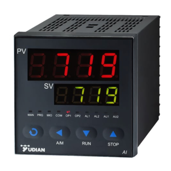
⑥ Data increase key, and also stop key 输 ⑦ LED indicator. MAN and PRG indicators is non-applicable ⑦ 入 for AI-518. PRO is on indicating the program of AI-518P is ⑥ , running. MIO, OP1, OP2, AL1, AL2, AU1 and AU2 indicate ⑥... - Page 22 Basic display status : When power on, the upper display window of the instrument shows the process value (PV), and the lower window shows the setpoint (SV). This status is called basic display status. When the input signal is out of the measurable range (for example, the thermocouple or RTD circuit is break, or input specification sets wrong), the upper display window will alternately display “orAL”...
-
Page 23: Parameter Setting Flow Chart
Parameter Setting Flow Chart Power on Password Field ① Parameters 2 Sec Next Parameter Process Value PV and set point SV Upper Limit Parameter Loc 2 Sec Alarm Incorrect password Entire Parameter Table Password correct Next Parameter Upper Limit Alarm 2 Sec... -
Page 24: Operation Description
2.3 Operation Description 2.3.1 Set Value Setting 、 In basic display status, if the parameter lock “Loc” isn't locked, we can set setpoint (SV) by pressing . Press key to decrease the value, key to increase the value, and key to move to the digit expected to modify. -
Page 25: Auto Tuning
“on” to “oFF”, press to confirm, then the auto tuning process will be cancelled. Note 1: AI-518 instruments apply the advanced artificial intelligence algorithm, which has avoided the overshoot problem of standard PID algorithm, and achieve precise control. Note 2: If the setpoint is different, the parameters obtained from auto-tuning are possibly different. So you’d better set setpoint to an often-used value or middle value first, and then start auto-tuning. - Page 26 Note 4: In a heating/refrigerating dual output system, auto tuning should be executed at the main output (OUTP). Note 5: AI series instrument has the function of self-adaptation. It is able to learn the process while working. The control effect at the first run after auto tuning is probably not perfect, but excellent control result will be obtained after a period of time because of self-adaptation.
-
Page 27: Parameters And Settings
3. PARAMETERS AND SETTINGS 3.1 Parameter Lock (Loc) and Field Parameters In order to protect important parameters from being modified by mistake, but also offer enough flexibility for field control, parameter lock (Loc) and field parameters are introduced. The parameters need to be displayed and modified in the work field are called Field Parameters. The set of field parameters is a subset of the entire parameter set, and can be freely chosen by the user. -
Page 28: The Entire Parameter Table
parameter. The EP paramters and Loc should be set as below: EP1=HIAL, EP2=HdAL, EP3=At, EP4=nonE, Loc=1 3.2 The Entire Parameter Table The parameters can be divided to 8 groups including alarm, control, input, output, communication, system, setpoint and field parameter definition. They are listed as below in sequence: Setting Code Name... - Page 29 0~200 Deadband Avoid frequent alarm on-off action because of the fluctuation of PV units 0: on-off control. For situation not requiring high precision; 1: AI MPt control. Allowed to quick activate auto-tuning (pressing in basic display status.) 2: AI MPt control. Activate auto-tuning. 3: After auto-tuning finished, the instrument automatically set CtrL=3, and quick auto-tuning function is disabled.
- Page 30 Parameter M5, P, t, CtI etc. are only for AI MPt control, and have no effect to on-off control. M5 is defined as measurement variation after output is changed by 5% (0.5mA if OP1=1) and when controlled process is basically stabilized. "5" indicates that output variation is 5 (5% or 0.5mA).
- Page 31 P is in reverse proportion to measurement variations caused by output changes by 100% in one second. It is defined as the following: if CtrL=1 or 3, then P=1000/measurement variation per second, the unit is 0.1 or 1 defined unit . Ex., instrument use 100% power to heat and there is no heat loss, if temperature 0~9999 in crease 1...
- Page 32 Parameter t is applied as one of the important parameters of AI artificial intelligence control algorithm. "t" is defined as follows: time needed for a electric furnace from the beginning of elevating temperature to get to 63.5% against the final speed of temperature elevating, provided there is no heat loss.
- Page 33 Small value can improve control accuracy. For SSR, thyristor or linear current output, it is generally 0.5 to 3 seconds. For Relay output or in a heating/refrigerating dual output control system, generally 15 to 40 seconds, because small value will cause the frequent on-off action of mechanical switch or frequent heating/refrigerating switch, and shorten its service life.
- Page 34 Spare 0~100mV voltage input 0~60mV voltage input Spare 0~500mV voltage input Spare 100~500mV voltage input extended input 1~5V voltage input specification 4 ~ 20mA (installed I4 in 0~5V voltage input MIO) 0 ~ 20mA (installed I4 in 0~10V MIO) Spare 2~10V 0~20V J (0~300.00℃) *Spare...
- Page 35 Note 1: For thermocouples or RTD input, only 0 or 0.0 is selectable, and the internal resolution is 0.1. dIP only affect the display, and has no affect to the accuracy of measurement or control. Signal scale Define scale low limit of input. It is also the low limit of transmitter output (CtrL=POP low limit or SOP) and light bar display.
- Page 36 4~20mA linear current output. Linear current output module should be installed to main output. oP1.A=5~7, No applicable in AI-518. oP1.A=8, single channel phase-shift output. K5 module should be installed. In this mode, AUX can not work as refrigerating output.
- Page 37 oP1.B=3, spare oP1.B=4, 4~20mA linear current output. Linear current output module should be installed to main output. AUX does not support position proportional output or phase-shift trigger output. For example, OUT and AUX all output 4~20mA linear current, then OPt=44. 0~110%: OPL is the minimum output of OUTP in single directional control system.
- Page 38 AUX output is 20mA, and user can’t limit the maximum AUX output to 10mA. Output upper OPL limits the maximum of OUTP (main output). OPH should be greater than OPL. 0~110% limit From right side to left side, the first, second, third and fourth digit of ALP individually indicate the alarm output terminal of HIAL, LoAL, dHAL, and dHAL.
- Page 39 C=1, it displays PV ( measurement value). D=0, The unit of program time is minute; D=1, the unit is second. For AI-518, C=0, The setpoint is restricted between LoAL and HIAL; C=1, no restriction on the setpoint.
- Page 40 window. It is helpful for user to know the cause of the alarm. G=1, disable alarm symbol display. H=0, unilateral hysteresis is applied; H=1, bilateral hysteresis is applied (in order to compatible with old version V6.X). For example: if it is expected that the instrument service as reverse action control; has the function of alarm suppressing at power on;...
- Page 41 The value of dL will determine the ability of filtering noise. There is one intermediate-value filter system and one second order integral digital filter system in AI series instrument. Intermediate value filter takes intermediate value among three continuous values, while integral filter has the same effect as resistance-capacity integral filter.
- Page 42 For AI-518P, parameter RUN is used to define the event-handling mode when program is running. Abrupt actions affecting control execution of program are called event, as the outcomes of events are always probably unpredicted, the aim of event handling is to turn those unpredicted things into predicted results.
- Page 43 planed. This mode guarantees constant running time of the program, but it can’t guarantee the integrity of the whole curve. D=1, With the function of PV startup and without the function of preparation. D=2 With the function of preparation and without the function of measurement value startup.
- Page 44 Loc can be set to other values than 808 in order to avoid field operators’ accidental modification of some important operation parameters. See the following: for AI-518 series instrument Loc=0, allowed to modify field parameters and setpoint. Loc=1, allowed to view field parameters, and to set setpoint. But the modification of field parameters (except parameter Loc itself) is not allowed.
- Page 45 1 to 8 field parameters can be defined by parameters EP1to EP8. If the number of the field parameters is less than 8, the first idle EP parameter should be set to “nonE”. The initial values of EPs and Loc are EP1=HIAL, EP2=LoAL, EP3=HdAL, EP4=LdAL, EP5=nonE, EP6=nonE, EP7=nonE, EP8=nonE and Loc=0.
-
Page 46: Additional Remarks Of Special Functions
3.3 Additional Remarks of Special Functions 3.3.1 Single-phase phase-shift trigger output When OPt is set to PHA, installing a K5 module in OUTP slot can single-phase phase-shift trigger a TRIAC or 2 inverse parallel SCRs. It can continuously adjust heating power by control the conduction angle of thyristor. With non-linear power adjustment according to the characters of sine wave, it can get ideal control. -
Page 47: Setpoints Switch
When number of the instruments is big enough, 2 or more computers can be used and built into a local network. AIDCS application software, a distributed control system software developed by Yudian, can control and manage 1~ 160 AI instruments, record the data, generate and print reports. If users want to develop their own distributed control system by themselves, the communication protocol of AI instruments can be free offered. - Page 48 3.3.5 Temperature re-transmitter / set current output Besides AI PID, stand PID control and on-off control, if the output is defined as current output, the instrument can also retransmit PV (process value) or SV (setpoint) into linear current and output from OUTP. The precision of current output is 0.2%FS.
Need help?
Do you have a question about the AI-518 and is the answer not in the manual?
Questions and answers