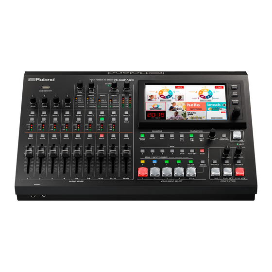
Roland VR-50HD MK II Reference Manual
Multi-format av mixer
Hide thumbs
Also See for VR-50HD MK II:
- Owner's manual (48 pages) ,
- Reference manual (18 pages) ,
- Startup manual (9 pages)
Table of Contents
Advertisement
Connect the ground terminal to an external ground point before use
In order to stabilize the connections between this unit and external devices, and to prevent malfunctions or faulty operation caused by static
electricity, you should connect the ground terminal of this unit to an external ground point before use. Use the included ground cord to make
this connection.
* Before connecting the ground cord or any external devices, you must minimize the volume of all devices and
turn off the power of all devices in order to prevent faulty operation or malfunctions.
* Unsuitable places for connection
5 Water pipes (may result in shock or electrocution)
5 Gas pipes (may result in fire or explosion)
5 Telephone-line ground or lightning rod (may be dangerous in the event of lightning)
* If you connect the ground terminal to an external ground point, a slight hum might occur.
Ground terminal
* If you do not understand how to connect the ground terminal, contact the nearest Roland Service Center.
© 2019 Roland Corporation
Reference Manual
01
Advertisement
Table of Contents

Related Manuals for Roland VR-50HD MK II


Summary of Contents for Roland VR-50HD MK II
- Page 1 * If you connect the ground terminal to an external ground point, a slight hum might occur. Ground terminal * If you do not understand how to connect the ground terminal, contact the nearest Roland Service Center. © 2019 Roland Corporation...
- Page 2 5 Roland is an either registered trademark or trademark of Roland Corporation in the United States and/or other countries. 5 Company names and product names appearing in this document are registered trademarks or trademarks of their respective owners.
-
Page 3: Table Of Contents
Contents Panel Descriptions Menu List Top Panel Audio Rear Panel Audio Ch. 1–4 Screen Audio Ch. 5/6–11/12 Screen Basic Operations Output Screen Turning the Power On/Off EQ/Dynamics Screen Operating the Menu 15Band EQ Screen Switching the Monitor View Modes Auto Mixing Screen Video Input/Output Settings Video Follows Audio Screen Reverb/Delay Screen... -
Page 4: Panel Descriptions
Panel Descriptions Top Panel Audio Mixer Section (Input channels 1–11/12, MAIN bus) [GAIN] knobs (p. 24) Adjust the gain (sensitivity) of the audio that is being input from the AUDIO IN 1–4 jacks. [SELECT] buttons Accesses a menu screen related to audio input and output. [SOLO] buttons (p. - Page 5 Panel Descriptions Common Controllers USB MEMORY port (p. 15, 34) Connect a USB flash drive here. It is used when loading a still image, or when saving or loading settings. PHONES jacks (Front panel) Connect headphones here. Two sets of headphones can be used simultaneously.
-
Page 6: Rear Panel
Panel Descriptions Rear Panel * To prevent malfunction and equipment failure, always turn down the volume, and turn off all the units before making any connections. Cord hook USB port AC adaptor jack Connect a USB flash drive here. This is used to update the system Connect the included AC adaptor to this jack. -
Page 7: Basic Operations
Basic Operations Turning the Power On/Off Operating the Menu Once everything is properly connected, be sure to follow the Here’s how to access the menu, and make video/audio settings and procedure below to turn on their power. If you turn on equipment in settings for this unit. -
Page 8: Switching The Monitor View Modes
Basic Operations Switching the Monitor View Modes This unit’s monitor provides four different view modes. Switch between these views as appropriate for your needs. Press one of the [MULTI-VIEW], [INPUT], [STILL] or [PGM] [INPUT] button (input mode) buttons. Shows the input videos in four quarters of the screen. A red border (tally border) is shown on the video that is being output as the program. -
Page 9: Video Input/Output Settings
Video Input/Output Settings List of Compatible Video Formats Input formats Output formats Frame rate Frame rate Video signal Video signal (connector name) When set to “59.94Hz” When set to “50Hz” When set to “59.94Hz” When set to “50Hz” (connector name) 480/59.94i 576/50i 480/59.94i... -
Page 10: Setting The Output Format
Video Input/Output Settings Setting the Output Format Assigning Video Sources Here’s how to specify the output format as appropriate for the device Here’s how to assign the video sources being input from the video that’s connected. input connectors to the VIDEO INPUT SELECT [1]–[4] buttons. Press the [MENU] button 0 touch Video <Output>. -
Page 11: Inputting Copy-Protected (Hdcp) Video
Video Input/Output Settings Inputting Copy-Protected (HDCP) Video If you want to input HDCP-protected video from a BD player or other device, you can enable HDCP input. * If you want to output copy-protected (HDCP) video or audio, connect a device that supports HDCP. Video/audio output restrictions What’s HDCP? If “HDCP”... -
Page 12: Assigning Video Buses To Output Connectors
Video Input/Output Settings Assigning Video Buses to Output Connectors This unit provides three video buses: PGM, PVW, and AUX. You can assign the video bus of your choice to each of the PGM and AUX connectors. PGM bus Outputs the video that reflects all processing such as video compositing that has been applied (the program video). Outputs the video that has been processed up to video compositing (the preview video). -
Page 13: Video Operations
Video Operations Switching the Video Outputting a Loaded Still Image Here’s how to switch between the Video input 1–4 video signals. A still image loaded into this unit can be assigned to the VIDEO INPUT SELECT [STILL] button, and output in the same way as video. In advance, assign the video sources as described in In advance, load a still image into this unit as described “Assigning Video Sources”... -
Page 14: Loading A Still Image
Video Operations Loading a Still Image You can load a still image, and output it in the same way as video (p. 13) or use it as a source for key compositing (p. 21) or a user logo (p. 17). There are two ways to load a still image: you can capture from output video, or you can load from a USB flash drive. -
Page 15: Loading A Still Image From A Usb Flash Drive
Video Operations Loading a Still Image from a USB Flash Drive Here’s how to load a still image from a USB flash drive into the unit. Touch <Load>. NOTE 5 Up to four still images can be temporarily saved in the unit. When you turn off the power, the still images are deleted. -
Page 16: Switching The Video Automatically (Video Follows Audio)
Video Operations Switching the Video Automatically Fading-In/Out the Program Output Video (Video Follows Audio) Here’s how to perform a fade-out from the program output video to a black screen, or a fade-in from a black screen to the program output This detects the audio that is input from a mic, and automatically video. -
Page 17: Freezing The Program Output Video (Freeze)
Video Operations Freezing the Program Output Video Inserting a Still Image in the Program (Freeze) Output (User Logo) You can temporarily freeze the program output video (freeze You can pause the program output, and output a still image of your function). -
Page 18: Video Composition Operations
Video Composition Operations About the Video Compositing Layer Hierarchy A video composited screen is created by a stack of layers. This unit lets you composite video by stacking up to three layers. The compositing effects available are fixed for each layer. Composition effect Explanation Picture-in-picutre (PinP) -
Page 19: Compositing Using Picture-In-Picture (Pinp)
Video Composition Operations Compositing Using Picture-in-Picture (PinP) Here’s how to composite an inset screen (a small separate screen) onto the background video. Inset screen Use the [VALUE] knob to adjust the size of the inset screen. Background video Press the [MENU] button to close the menu screen. Press one of the VIDEO INPUT SELECT [1]–[4] buttons to select the background video. -
Page 20: Compositing Two Inset Screens
Video Composition Operations Compositing Two Inset Screens By using PinP compositing on the PinP/KEY layer, you can show two inset screens beside each other. Use the [VALUE] knob to adjust the size of the inset screen. Composite the video as described in “Compositing Using Picture-in-Picture (PinP)”... -
Page 21: Compositing Using Key
Video Composition Operations Compositing Using Key Here’s how you can turn a portion of the video transparent and composite it with the background video. You can use luminance key with either a black or a white background, or a chroma key with either a blue or green background. Compositing a Logo or Image (Luminance Key) You can cut out a logo or image by turning its black or white portion transparent, and then superimpose it on the background video. -
Page 22: Compositing A Subject And Background (Chroma Key)
Video Composition Operations Compositing a Subject and Background (Chroma Key) You can cut out a video by turning its blue or green portion transparent, and then superimpose it on the background video. This lets you composite a subject that’s photographed against a blue background or green background. Video to be Use the PinP/KEY [KEY LEVEL] knob to adjust the degree superimposed... -
Page 23: Compositing A Still Image Loaded Into The Unit
Video Composition Operations Compositing a Still Image Loaded into the Unit (Luminance/Chroma Key) A portion of a still image loaded into this unit can be made transparent, and composited with the background video. * The still image assigned to the VIDEO INPUT SELECT [STILL] button is used as the source image. In the <Detail>... -
Page 24: Audio Operations
Audio Operations Assigning Audio Sources to Audio Channels Adjusting the Input Gain (Sensitivity) Audio from video input (HDMI, SDI), line input, or mic can be Here’s how to adjust the input gain so that the audio is at the assigned to channels 5/6–11/12. appropriate level. -
Page 25: Adjusting The Volume Balance
Audio Operations Adjusting the Volume Balance Correcting a Time Difference Between Video and Audio (Delay) Here’s how to adjust the volume balance of each input and the overall volume. If there is a timing discrepancy between the video and audio, you can correct the output timing by delaying the audio output. -
Page 26: Applying Effects To Input Audio
Audio Operations Applying Effects to Input Audio You can apply effects to the input audio to adjust the character of the sound. The following table shows the effects that are available. Reverb Gate Compressor Equalizer High-pass filter Voice changer Anti-feedback Input audio Channels 1–4 Channels 5/6, 7/8 (MIC) -
Page 27: Applying Effects To Output Audio
Audio Operations Applying Effects to Output Audio Interlinking Audio Output to Video Switching (Audio Follow) Here’s how to modify the tonal character by applying effects to the audio output. You can use compressor, limiter, and two types of equalizer. Here’s how the audio output can be automatically switched in tandem with video switching (the Audio Follow function). -
Page 28: Controlling Volume Levels Automatically (Auto Mixing)
Audio Operations Controlling Volume Levels Automatically Checking a Specific Audio (Solo) (Auto Mixing) Here’s how you can temporarily monitor only specific audio in the headphones (the solo function). This automatically controls the volume that normally are adjusted by an operator using the faders (Auto Mixing funcition). Press the [SOLO] button of the channel that you want to It lets you rely on this unit to perform complex volume-adjustment solo, turning the solo function on (lit). -
Page 29: Outputting Aux-Bus Audio
Audio Operations Outputting AUX-bus Audio This unit has three audio buses: MAIN, AUX 1, and AUX 2. You can assign a desired bus to each output connector. For example, in a live event, you might output a mix of all audio inputs (the MAIN bus), while separately outputting a mix of only specific audio inputs (the AUX 1 bus) for recording or streaming. -
Page 30: Remotely Controlling A Camera
Remotely Controlling a Camera You can connect up to six cameras via the LAN port and remotely control them from this unit. Remote cameras made by JVC and Panasonic are supported. * Refer also to the owner’s manual of your camera. Network Settings on the Camera Registering Camera Settings in a Preset In order to control a camera from this unit, you need to make... - Page 31 Remotely Controlling a Camera Recalling from a Single Camera > 0 <Store> to make it light red. Touch < Press the [MENU] button 0 < > 0 Network <Camera Control> 0 touch <All Camera Recall> to turn it “OFF.” In “Camera Preset,” touch the preset number in which you want to register the settings.
-
Page 32: Live Streaming
* In order for the audio and video from this unit to be correctly viewed on the computer, software that supports the USB video class and USB audio class must be installed on the computer. * For the latest operating requirements, refer to the Roland website (https://proav.roland.com/). Turn on the power to this unit. -
Page 33: Other Features
Other Features Saving/Recalling Settings (Memory) You can save the current settings, including the video/audio settings and the state of the operating panel, in memory and recall those settings for use when necessary. This unit is provided with eight memories. About the Last Memory function This unit has a built-in Last Memory feature. -
Page 34: Saving The Unit's Settings On A Usb Flash Drive
Other Features Saving the Unit’s Settings on a USB Flash Drive You can group together the unit’s settings into a single file (.V50) and save it to a USB flash drive connected to the USB MEMORY port. You can access the saved setting file on the USB flash drive and load it into the unit for use when needed. Overwrite-saving NOTE 5 When using a USB flash drive for the first time, you must... -
Page 35: Formatting A Usb Flash Drive
Other Features Formatting a USB Flash Drive Renaming the Monitor Label The first time that you use a USB flash drive, you must use this unit to You can rename the labels that are shown on the monitor for the format it. -
Page 36: Returning To The Factory Settings (Factory Reset)
Other Features Returning to the Factory Settings (Factory Reset) Here’s how you can return the settings of this unit to their factory-set state. If following the procedures described in this manual does not cause the result you expect, try executing a factory reset. NOTE 5 When you execute factory reset, any previously specified content, any settings saved in memory (p. -
Page 37: Menu List
Menu List Audio Audio Ch. 1–4 Screen (Press a channel 1–4 [SELECT] button, or [MENU] button 0 Audio <1>–<4>) These settings adjust the input audio of channels 1–4. Menu item Value Explanation (bold text: default value) +48V OFF, ON Turns the phantom power on/off. If this is “ON, ” phantom power is supplied via the AUDIO IN jacks (XLR). Solo OFF, ON Turns the solo function on/off. - Page 38 Menu List Menu item Value Explanation (bold text: default value) Equalizer When you touch <Edit>, a detailed screen for the effect appears. Turns the equalizer on/off. Equalizer OFF, This is a 4-band parametric equalizer. It lets you shape the character of the sound by boosting Effect or cutting four frequency regions.
-
Page 39: Audio Ch. 5/6-11/12 Screen
Menu List Audio Ch. 5/6–11/12 Screen (Press a channel 5/6–11/12 [SELECT] button, or [MENU] button 0 Audio <5/6>–<11/12>) These settings adjust the input audio of channels 5/6–11/12. Menu item Value Explanation (bold text: default value) Turns the Audio Follow function on/off. Audio follow is a function that automatically switches the audio output in tandem with video switching. - Page 40 Menu List Menu item Value Explanation (bold text: default value) Compressor When you touch <Edit>, a detailed screen for the effect appears. Turns the compressor on/off. Audio that exceeds the specified threshold level is compressed. This reduces the difference Compressor OFF, ON Effect between the maximum volume and minimum volume, making the audio more comfortable for...
-
Page 41: Output Screen
Menu List Output Screen (Press the MAIN [SELECT] button, or [MENU] button0Audio <Output>) Here you can make settings for the output audio. Menu item Value Explanation (bold text: default value) MAIN Adjusts the main output audio. Adjusts the output volume. Level -Inf–... -
Page 42: Eq/Dynamics Screen
Menu List EQ/Dynamics Screen ([MENU] button0Audio <EQ/Dynamics> 0 <Edit>) Here you can make settings for the four-band parametric equalizer. It lets you shape the character of the sound by boosting or cutting four frequency regions. Menu item Value Explanation (bold text: default value) MAIN Adjusts the main output audio. -
Page 43: 15Band Eq Screen
Menu List 15Band EQ Screen ([MENU] button0Audio <15Band EQ>) Here you can make settings for the 15-band graphic equalizer. It lets you shape the character of the sound by boosting or cutting each of the 15 frequency regions into which the sound is divided. Menu item Value Explanation... -
Page 44: Video Follows Audio Screen
Menu List Video Follows Audio Screen ([MENU] button 0 Audio <Video Follows Audio>) Here you can make settings for the Video Follows Audio function. Menu item Value Explanation (bold text: default value) Turns the Video Follows Audio function on/off. “Video follows audio” is a function that detects audio Video Follows OFF, ON input from the mics, and switches to the desired video according to the volume. -
Page 45: Video
Menu List Video Video Input 1–4 Screen ([MENU] button 0 Video <1>–<4>) When Input Assign=HDMI Adjusts the video that is input from the HDMI IN connector. Menu item Value Explanation (bold text: default value) Scaling Specifies the scaling type. Full Always displays the picture expanded to full screen, irrespective of the aspect ratio of the input video. - Page 46 Menu List Menu item Value Explanation (bold text: default value) Color Correction Brightness -64–0– +63 Adjusts the brightness. Contrast -64–0– +63 Adjusts the contrast. Saturation -64–0– +63 Adjusts the saturation. -64–0– +63 Adjusts the red level. Green -64–0– +63 Adjusts the green level. Blue -64–0–...
-
Page 47: Video Input Still Screen
Menu List Video Input Still Screen ([MENU] button0Video <Still>) Here you can make settings for still images loaded into the unit. Menu item Value Explanation (bold text: default value) Touch to access the Still Select screen. Selects the still image that is assigned to the VIDEO INPUT SELECT [STILL] button. Still 1–4 * When the [SELECT] button is lit red, you can also use the STILL/INPUT SOURCE [1]–[4] buttons to... -
Page 48: Input Assign Screen
Menu List Menu item Value Explanation (bold text: default value) Selects the video that is sent to the AUX bus. * You can also use the AUX [1]–[PGM] buttons to select this. Input 1–4 Video being input to Video Input 1–4 AUX Bus Source PinP Source video of the PinP layer... -
Page 49: Composition Setup Screen
Menu List Composition Setup Screen ([MENU] button0Video <Composition Setup>) Here you can make settings for video composition. Menu item Value Explanation (bold text: default value) Preview PinP, PinP KEY, STILL KEY Selects the layer for preview display. Edit PinP, PinP KEY, STILL KEY Selects the layer for editing. - Page 50 Menu List PinP screen Menu item Value Explanation (bold text: default value) PinP OFF, Enables (ON) or disables (OFF) PinP settings. 0–100.0% Size 10.0–25 Adjusts the size (zoom) of the inset screen. 0– +100.0% Position H -100.0– Adjusts the horizontal position of the inset screen. 0–...
- Page 51 Menu List PinP/KEY screen PinP Menu item Value Explanation (bold text: default value) PinP OFF, Enables (ON) or disables (OFF) PinP settings. Size 10.0–25 0–100.0% Adjusts the size (zoom) of the inset screen. Position H -100.0– 0– +100.0% Adjusts the horizontal position of the inset screen. Position V -100.0–...
-
Page 52: Test Pattern Screen
Menu List Test Pattern screen (Press the [MENU] button0touch Video <Test Pattern>) Menu item Value Explanation (bold text: default value) OFF, 75% Color Bar. 100% Color Bar Test Pattern Specifies the test pattern. Ramp, Step, Hatch, Frame Test Tone OFF, ON Turns the test tone on/off. -
Page 53: System
Menu List System USB Streaming Screen ([MENU] button0< >0System <USB Streaming>) Here you can make settings for video and audio that are output via USB. Menu item Value Explanation (bold text: default value) Audio Level -INF–0 0– +12.0dB Adjusts the volume of the USB output. MAIN, AUX 1, AUX 2 Audio Bus Specifies the audio bus that is assigned to the USB STREAMING port. -
Page 54: Setup Screen
Menu List Setup Screen ([MENU] button0< >0System <Setup>) Here you can make system-related settings. Menu item Value Explanation (bold text: default value) Specifies whether HDCP is enabled (ON) or disabled (OFF). When set to “ON, ” copyright-protected (HDCP) HDCP OFF, ON video can be input. -
Page 55: Network
Menu List Network LAN Screen ([MENU] button0< >0Network <LAN>) Here you can make network-related settings. Menu item Value Explanation (bold text: default value) Status — Displays the connection status. IP Address — Displays the IP address. MAC Address — Displays the MAC address. Subnet Mask —... - Page 56 Menu List Camera Setup screen Menu item Value Explanation (bold text: default value) 1–6 Camera ID Selects the camera to be controlled. N/A, JVC, Panasonic Protocol Specifies the camera’s protocol. If the “Protocol” is “JVC, ” touch this to access a screen where you can enter a login name. Enter the Login Name —...
-
Page 57: Lan/Rs-232C Command Reference
LAN/RS-232C Command Reference This unit support two types of remote-interface communication: LAN and RS-232C. Using the LAN port or RS-232C connector to send specific commands to this unit from a controlling device lets you operate this unit remotely. LAN Interface RS-232C Interface RS-232C connector pin layout Pin assignments... -
Page 58: List Of Commands
LAN/RS-232C Command Reference List of Commands * When sending a sequence of commands to this unit from a controller, after each one, be sure to verify that an “ACK” response is returned before sending the next command. Sent Response Item Parameter command command... - Page 59 LAN/RS-232C Command Reference Commands spontaneously sent from this unit Sent Response Item Parameter command command Send status of the VIDEO INPUT SELECT stxPGM:a; stxQPG:a; a: 0 (INPUT 1), 1 (INPUT 2), 2 (INPUT 3), 3 (INPUT 4), 4 (STILL) buttons * This is enabled when the unit receives the command “stxCPG: 1;.
-
Page 60: Appendices
Appendices Troubleshooting If you suspect a malfunction, please check the following points. If this does not resolve the problem, contact a nearby Roland Service Center. Problem Items to check Action Page Video-related problems Could you be inputting copy-protected If you want to input copy-protected (HDCP) video, set “HDCP”... -
Page 61: Main Specifications
Appendices Main Specifications Roland VR-50HD MK II: Multi-format Video Mixer 9 Video 4:4:4 (RGB), 10-bit Video Processing 4:4:4 (Y/Pb/Pr), 10-bit BNC type x 4 SDI IN 1–4 connectors * Conforms to SMPTE 424M (SMPTE 425M-AB), 292M, 259M-C. HDMI type A x 4 Input Connectors HDMI IN 1–4 connectors... - Page 62 Startup Guide, Leaflet “USING THE UNIT SAFELY, ” AC adaptor, Power cord, Ground cord * 0 dBu = 0.775 Vrms * This document explains the specifications of the product at the time that the document was issued. For the latest information, refer to the Roland website.
-
Page 63: Dimensions
Appendices Dimensions Unit: mm... -
Page 64: Video Block Diagram
Appendices Video Block Diagram HDMI MULTI-VIEW MULTI-VIEW AUX Bus source PinP PinP/KEY USB Memory Still Memory OUTPUT CAPTURE VIDEO FOLLOWS AUDIO AUDIO input 1–4, 5, 7 (1–4) USER LOGO OUTPUT CAPTURE Input Assign Input Select USER LOGO OUTPUT HDMI EDID Emulator INPUT 1 SDI PGM (*1) -
Page 65: Audio Block Diagram
Appendices Audio Block Diagram INPUT BUS OUT BUS MAIN REVERB AUX 1 AUX 2 SOLO AUX 1 AUX 2 SOLO MONO METER SDI OUT PGM (*1) MIC Input AUTO CH 1–4, 5, 7 GATE COMP 4-BAND EQ Voice changer DELAY MIXING Anti-feedback MUTE...
Need help?
Do you have a question about the VR-50HD MK II and is the answer not in the manual?
Questions and answers