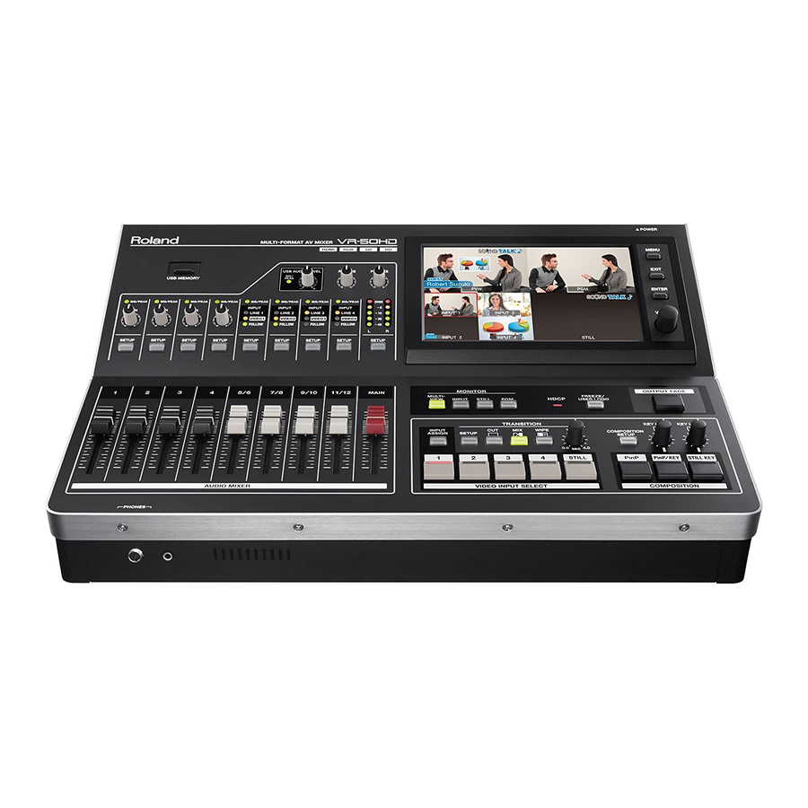
Roland VR-50HD Owner's Manual
Multi-format av mixer
Hide thumbs
Also See for VR-50HD:
- Reference manual (65 pages) ,
- Startup manual (9 pages) ,
- Information (4 pages)
Table of Contents
Advertisement
Use the latest version of the system program for the VR-50HD.
Owner's Manual
(this document)
Read this first. It explains the basic things you need to know in order to
use the VR-50HD.
PDF Manual
(download from the Web)
• Reference Manual
This explains all parameters of the VR-50HD.
It also describes the settings to make when operating the unit by
remote control.
Default setting of the system frame rate is 59.94 Hz.
NOTE
When you want to operate in the Frame Rate of 50 Hz, you can set it at the
System screen.
To obtain the PDF manual
The latest information on the system program
1.
Enter the following URL in your computer.
http://www.rolandsystemsgroup.net/
2.
Choose "VR-50HD" as the product name.
Advertisement
Table of Contents

Subscribe to Our Youtube Channel
Related Manuals for Roland VR-50HD


Summary of Contents for Roland VR-50HD
- Page 1 NOTE When you want to operate in the Frame Rate of 50 Hz, you can set it at the System screen. Use the latest version of the system program for the VR-50HD. To obtain the PDF manual Owner’s Manual The latest information on the system program (this document) Read this first.
-
Page 2: Using The Unit Safely
Refer all servicing to your retailer, at the installation matches the power. When the power needs to the nearest Roland Service Center, or an input voltage specified on the AC be completely turned off, turn off authorized Roland distributor, as listed on the the power switch on the unit, then pull out the adaptor’s body. - Page 3 Roland Service Center, or an by using a dry cloth to wipe all dust Take care not to get burned authorized Roland distributor, as listed on the and other accumulations away from The area of SDI connectors on the “Information” sheet when: its prongs.
-
Page 4: Important Notes
Do not use this device in stored in the unit. developed by Technology Properties Limited the vicinity of such receivers. • Roland assumes no liability concerning the (TPL). Roland has licensed this technology restoration of any stored content that has from the TPL Group. -
Page 5: Table Of Contents
(e.g., includes newer sounds), so what you actually see in the display may not always match what appears in the manual. Copyright © 2013 ROLAND CORPORATION All rights reserved. No part of this publication may be reproduced in any form without the written permission of ROLAND CORPORATION. -
Page 6: Panel Descriptions
This displays the inputs from the respective source devices and the output of the VR-50HD. The monitor is a touch panel, and you can switch the video and make settings for Picture-in-Picture by touching the screen. -
Page 7: Video Mixer Section
These call up the channel parameter screen for their respective channels and display it on the monitor. p. 29 This indicates the audio output level of the VR-50HD. If OVER lights up, distortion might occur. Adjust the output to Level meter p. -
Page 8: Rear Panel
No . Name Explanation Page [POWER] switch This turns the power to the VR-50HD on and off. p. 12 Here you connect a device used for remote control (such as a computer equipped with a functional RS-232C RS-232C connector interface). -
Page 9: Monitor Display
You use the MONITOR [MULTI-VIEW]–[PGM] buttons to switch the displayed view. MULTI-VIEW This displays the various inputs and outputs of the VR-50HD. The channel currently being output is displayed with a red border. You can change the output by touching the input screen. -
Page 10: Signal Flow
Panel Descriptions Signal Flow Signal flow inside the VR-50HD is as shown in the figure below. Video signals HDMI MULTI-VIEW MULTI-VIEW AUX Bus Source MIXER OUTPUT USB Memory Still Memory USER LOGO Input Assign Input Select MIXER OUTPUT INPUT 1... - Page 11 Panel Descriptions USER LOGO Output Bus SDI PGM Freeze/ Output User Logo Fade SDI AUX OUTPUT HDMI PGM HDMI AUX STILL KEY PinP PinP/KEY RGB/COMPONENT PGM RGB/COMPONENT AUX USB STREAMING When HDCP is set to ON (p. 23), no audio and video signals are output from these connectors.
-
Page 12: Preparations For Power-Up
First connect the AC adaptor to the AC adaptor connector on the VR-50HD, and then plug the power cord into a power outlet. Turning the power on * Before turning the unit on/off, always be sure to turn the volume down. -
Page 13: Menu Operations
You use the [MENU] button and the [VALUE] knob, or the touch panel, to make various settings. MEMO For detailed information on menu items, refer to the “Reference Manual” (PDF) for the VR-50HD, which can be downloaded from the following Roland website. -
Page 14: Connecting External Equipment
If you are unsure of the connection method, contact the nearest Roland Service Center, or an authorized Roland distributor, as listed on the “Information” sheet. AUDIO IN 1–4 connectors... -
Page 15: Connecting Video Source Equipment
Connecting External Equipment Connecting Video Source Equipment NOTE After making the connections, be sure to press the [INPUT ASSIGN] button and select the desired video input connectors for channels 1–4 (p. 16). Making HDMI Connections Making RGB/Component Connections Connect video cameras and other devices provided with HDMI Connect computers provided with analog RGB output to the RGB/ output to HDMI IN connectors 1–4. -
Page 16: Assigning Video Sources To Channels
Connecting External Equipment Assigning Video Sources to Channels You assign video connectors receiving input to channels 1–4. Press the [INPUT ASSIGN] button . The names of selectable video connectors are displayed over the video on channels 1–4. Touch a connector name to assign the chosen video connector to the channel . -
Page 17: Connecting Audio Source Equipment
Connecting External Equipment Connecting Audio Source Equipment * Channels 1–4 are mono, and channels 5–12 operate as stereo pairs. Connecting Microphones Connecting Playback Equipment Connect microphones to AUDIO IN connectors 1–4. You connect audio output from equipment such as video decks and CD players to the AUDIO IN jacks. -
Page 18: Using Phantom Power
Connecting External Equipment Using Phantom Power Assigning HDMI/SDI Audio to Channels Channels 1–4 are exclusively for analog input, but channels NOTE 5/6–11/12 can also be assigned to audio input via HDMI or SDI. • Always turn the phantom power off when connecting any Use the following procedure to change assignments. -
Page 19: Connecting Output Equipment
XLR and RCA phono type, and you can select the bus for the audio that is output from the respective connectors/jacks (p. 30). * On the VR-50HD, the nominal output level is +4 dBu for the XLR type connectors and -10 dBu for the RCA phono type jacks. -
Page 20: Connecting A Computer For Streaming
Installing a special driver is not • Windows 7 necessary. • Windows 8 * The computer recognizes the VR-50HD as a USB video device or • Mac OS X 10.7 or later USB audio device. * Connection and operation of the VR-50HD with standard... -
Page 21: Outputting Streamed Video And Audio To A Computer
Outputting Streamed Video and Audio to a Computer NOTE For the video and audio signals from the VR-50HD to be viewed and heard correctly on the computer, software that supports USB video class and USB audio class must be installed and set up on the computer. -
Page 22: Input Formats/Output Formats
Here you set the format of the signal output from the video output connectors (RGB/COMPONENT, HDMI, and SDI). You can input signals of different formats via INPUT 1–4 on the VR-50HD. Display the menu screen (p . 13) . Signals of the formats shown below can be input via the respective INPUT 1–4 connectors. -
Page 23: Inputting Hdcp Signals
Inputting HDCP Signals By default, support for HDCP (High-bandwidth Digital Content Protection) on the VR-50HD is set to OFF. This means that HDCP-applied signals, such as from Blu-ray Disc players, cannot be input. When inputting signals to which HDCP is applied, follow the procedure shown below to change the setting. -
Page 24: Video Operations
. Input from the source equipment (channels 1–4) is displayed on the monitor. Upon startup, the VR-50HD sets channel 1 as the default selected channel and channel 1 is displayed with a red border. MEMO Pressing the TRANSITION [SETUP] button displays the detailed setup screen. -
Page 25: Switching The Video Using Buttons
Press one of the VIDEO INPUT SELECT [1]–[4] buttons to select the input channel you want to output from the Applying a Fade-out VR-50HD . Pressing the [OUTPUT FADE] button starts a fade-out. The button indicator flashes while the fade is in progress. -
Page 26: Compositing Video
Video Operations Compositing Video Three video-composition modes are available. * If you’re using STILL KEY, then it’s necessary beforehand to use the procedure on p. 35 to assign a still image to the VIDEO INPUT SELECT [STILL] button. Mode Explanation PinP This displays an inset screen against a background (Picture-in-Picture). -
Page 27: Compositing Using Picture-In-Picture (Pinp)
Video Operations Compositing Using Picture-in-Picture Compositing Using a Key (PinP/KEY) (PinP) You can perform compositing such as “chroma key” and “luminance key” that superimposes video in which a specified color is transparent onto a background video. This displays an inset screen against a background. You can also use picture-in-picture simultaneously with key compositing. -
Page 28: Compositing A Still Image (Still Key)
Video Operations Touch <Level>, then use the [VALUE] knob to adjust the MEMO range of color to make transparent . • Going to the COMPOSITION setting screen and touching * Setting Hue, Saturation, and Gain to 0 can make adjustment <Detail>... -
Page 29: Audio Operations
Audio Operations Channel Parameter Screen Pressing the [SETUP] button for a channel displays the channel parameter screen. The information displayed on the screen differs for channels 1 to 4, channels 5/6 to 11/12, and MASTER (output). Procedure Channels 1–4 Press the [SETUP] button for the channel whose settings you want to make . - Page 30 Audio Operations Channels 5/6–11/12 MAIN (Output) Parameter Explanation Parameter Explanation Follow This switches the Audio Follow function on or off. This adjusts the output level of the MAIN bus. You can MAIN Level also use the [MAIN] fader on the top panel to adjust When listening to audio through headphones, you this.
-
Page 31: Adjusting The Audio Balance
Audio Operations Adjusting the Audio Balance Adjusting the Final Audio Output You can use the [MAIN] fader to adjust the volume level of the final NOTE output. Operate the fader while watching the level meter. The [MAIN] fader adjusts the output level of the MAIN bus only. The output level of the AUX bus can be adjusted independently (p. -
Page 32: Aligning The Timing Of Video And Audio (Lip-Sync)
Switch the video channels . On the VR-50HD by itself, video processing requires about two frames of time. (This varies according to the input and output When a video channel where Audio Follow is on is switched, the formats.) -
Page 33: Applying Effects To Audio
Audio Operations Mastering Applying Effects to Audio This adjusts the dynamic range and tone quality. On the VR-50HD, you can apply effects (Reverb, Equalizer, and Mastering) to audio output. Parameter Explanation Mastering ON/OFF This switches mastering on and off. High This suppresses high-frequency distortion. -
Page 34: Other Functions
Formatting Formatting USB Flash Drives Display the menu screen (p . 13) . To use a USB flash drive, it must first be formatted on the VR-50HD. NOTE Touch System <Memory> . • USB flash drives not formatted using the VR-50HD are not The Memory screen appears. -
Page 35: Using Still-Image Files
Using Still-image Files The File Select screen appears. On the VR-50HD, you can assign a still image to the VIDEO INPUT SELECT [STILL] button and work with it in the same way as video. You import the still-image file from a USB flash drive that you connect to the VR-50HD. -
Page 36: Outputting A User Logo
Other Functions Outputting a User Logo Freezing the Output Screen You can make the setting so that pressing the [FREEZE/USER LOGO] You can make the setting so that pressing the [FREEZE/USER LOGO] button stops video output and outputs a still image you want to button freezes the output screen. -
Page 37: Changing The Screen Labels
The Label screen appears. Value Explanation The PGM bus is assigned. This is the final video signal processed by the VR-50HD itself. The PVW bus is assigned. This is a video signal allowing previewing of the results up through video compositing. -
Page 38: Selecting The Signal Of The Aux Bus
Other Functions Selecting the Signal of the AUX Bus Capturing Video Being Output You can capture images from video as it is being output. Display the menu screen (p . 13) . You can take captured video images and use them as still images for user logos or in luminance-key processing. -
Page 39: Saving/Recalling Settings
Other Functions Recalling settings Saving/Recalling Settings * The settings at Memory No. 1 are called up automatically at You can take the current settings, including the panel state, audio power-up. settings, and video settings, and save them in the unit’s internal memory as a single set, then call them up for use when needed. -
Page 40: Saving Settings On A Usb Flash Drive/Importing Settings From
Touch USB Memory <Load> . file. The File Select screen appears. You can also import such a file saved on a USB flash drive into the VR-50HD. Saving settings Display the menu screen (p . 13) . Touch System <Memory> . -
Page 41: Returning To The Factory-Default Settings (Factory Reset)
Other Functions Returning to the Factory-default Settings (Factory Reset) You can return the settings on the VR-50HD to their factory-default values. This is called a “factory reset. ” NOTE Performing a factory reset causes all user data saved in the unit to be lost. -
Page 42: Appendix
DC 12 V–16 V. adaptor. The unit gets extraordinary hot Immediately stop using the unit, and request servicing by your The cooling fan malfunction. retailer, the nearest Roland Service Center, or an authorized Roland — distributor, as listed on the ”Information” sheet. -
Page 43: About Remote Control
Appendix About Remote Control The VR-50HD can be operated remotely from an external RS-232C or MIDI device. For more information about remote control, download the “Reference Manual” (PDF) from the following Roland website. http://www.rolandsystemsgroup.net/ About MIDI VISUAL CONTROL The VR-50HD can be operated remotely from a device that supports MIDI Visual Control. -
Page 44: Main Specifications
Appendix Main Specifications Roland VR-50HD: MULTI-FORMAT AV MIXER Processing 4: 4: 4 (RGB), 10-bit (Internal processing) 4: 2: 2 (Y/Pb/Pr), 10-bit Video BNC type x 4 (INPUT 1–4) 3G/HD/SD-SDI * Conforms to SMPTE 424M (SMPTE 425M-AB), 292M, 259M-C. Type A (19 pin) x 4 (INPUT 1–4) HDMI (DVI-D) * HDCP Supported. - Page 45 Appendix Audio AUDIO IN (1 to 4) jacks (XLR/TRS combo type) * XLR type: 1 GND, 2 HOT, 3 COLD * Phantom Power: DC 48 V (unloaded maximum), 5 mA (maximum load) (Current value per channel). Input Connectors AUDIO IN (5 to 8) jacks (RCA phono type) AUDIO IN (9 to 12) jacks (TRS Type) AUDIO OUT L, R jacks (XLR-3-32 type) * XLR type: 1 GND, 2 HOT, 3 COLD...
-
Page 46: Index
Index Audio Follow ........32 Mastering ........33 [USB AUDIO LEVEL] knob . - Page 47 For the U.K. IMPORTANT: THE WIRES IN THIS MAINS LEAD ARE COLOURED IN ACCORDANCE WITH THE FOLLOWING CODE. BLUE: NEUTRAL BROWN: LIVE As the colours of the wires in the mains lead of this apparatus may not correspond with the coloured markings identifying the terminals in your plug, proceed as follows: For EU Countries The wire which is coloured BLUE must be connected to the terminal which is marked with the letter N or coloured BLACK.
- Page 48 For EU Countries For China...
Need help?
Do you have a question about the VR-50HD and is the answer not in the manual?
Questions and answers