Advertisement
WARNINGS AND CAUTIONS
• WARNING: TO AVOID SERIOUS PERSONAL INJURY never push
objects of any kind into this product through openings, as they may touch
dangerous voltages.
• WARNING: TO AVOID SERIOUS PERSONAL INJURY never touch
uninsulated wires or terminals unless the wiring has been disconnected at
the network interface.
• Read and understand all instructions. Follow all warnings and instructions
marked on the product.
DESCRIPTION
Leviton Quantran mBus control stations are a flexible, easy to configure control interface to Quantran mBus load control devices. Offered in multiple scene
configurations and finishes, a device is available to fit every lighting control need.
POWER CONSIDERATIONS
Input: mBus Stations Require 8-18VDC
Current draw: 10mA
Standard dc Voltage Drop calculations should be used to ensure that your
voltage is always greater than the minimum. If you're using 18AWG Belden
1502R with a resistance of 0.0069ohms/foot, the following formula can be
used:
Vdrop=Total Load (Amps) * Run Length (Feet) * 0.0069 Ohms/Foot
NOTE: Assuming you're using a 12Vdc Supply, and you'll allow a voltage drop
of 12V-8V=4V, the formula can be simplified to:
Max Run (Feet) =4/(Total Load (Amps)*0.0069)
INSTALLATION
• Product is designed to fit into a single gang 3" x 3" back box, not included.
• Follow best industry practices for installation
• Product requires commissioning by a Leviton field commissioning agent
after installation.
NOTE: The mounting surface must be flat to avoid distortion of the back plate,
which may prevent the cover plate fitting correctly. For the same reason, do
not over-tighten the fixing screws.
TERMINATIONS
Use RS485 compatible cable for communications. RS-485 requires a single
Twisted Pair, 24 AWG minimum.
• Connect Data+, Data-, Common, +V, and shield at every station (see
Table 1).
• Do not splice control wire
• Shield shall be connected to ground at the dimmer rack and must only be
connected to ground at one point in the system.
• Capacitance of wire shall be 15pF/ft. or less.
• Normal Impedance of wire shall be between 100-120 ohms.
• A second pair of stranded wire is required for the power.
• We strongly recommend the use of either Leviton #WIRLN-500, Belden
1502R, or equivalent be used for wire runs.
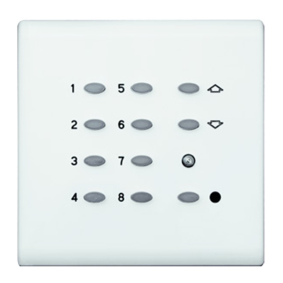
OPERATION
• Scene buttons are used to recall pre-programmed scenes. Reference
dimmer modules installation instructions for details on programming.
• Raise/Lower buttons are used to raise or lower the last selected scene.
• Off turns the lights off.
• The IR Receiver can be used with the IR remote to execute the above
functions.
Pin #
1
2
3
4
mBus Control Stations
Cat. Nos. QTM00-050 (5-Button), QTM00-090 (9-Button)
INSTALLATION
Function
Data +
Data -
Common
+V
WARNINGS AND CAUTIONS
• Never install communications wiring or components during a lightning storm.
• Never install communications components in wet locations unless the
components are designed specifically for use in wet locations.
• Use caution when installing or modifying communications wiring or
components.
• Do not use this product near water - e.g., near a tub, wash basin, kitchen
sink or laundry tub, in a wet basement, or near a swimming pool.
• SAVE THESE INSTRUCTIONS.
B1
B2
B3
B4
Buttons
1-8
Table 1
Notes
Connect on every station, use one conductor of a twisted pair
Connect on every station, use the second conductor of a twisted pair
Connect on every station – even if not using power
+12-24Vdc
QTM00-050
QTM00-090
DI-000-QTM00-00A
ENGLISH
Raise
Lower
IR Receiver
Off
Clip on
Face plate
Raise
Lower
IR Receiver
Off
Clip on
face plate
Advertisement
Table of Contents

Related Manuals for Leviton Quantran QTM00-050


Summary of Contents for Leviton Quantran QTM00-050
- Page 1 • SAVE THESE INSTRUCTIONS. DESCRIPTION Leviton Quantran mBus control stations are a flexible, easy to configure control interface to Quantran mBus load control devices. Offered in multiple scene configurations and finishes, a device is available to fit every lighting control need.
- Page 2 LIMITED 2 YEAR WARRANTY AND EXCLUSIONS Leviton warrants to the original consumer purchaser and not for the benefit of anyone else that this product at the time of its sale by Leviton is free of defects in materials and workmanship under normal and proper use for two years from the purchase date. Leviton’s only obligation is to correct such defects by repair or replacement, at its option.
Need help?
Do you have a question about the Quantran QTM00-050 and is the answer not in the manual?
Questions and answers