Advertisement
RL1 RL2 PRG
F
8. 8 . 8 . 8
E-2000M
8. 8 . 8 . 8
PROCESS CONTROLLER
USER MANUAL
Elimko
2000M
E-2000M series universal process controllers are advanced new generation
microcontroller based industrial instruments designed for On/Off and PID
control forms, dimensions of 96X96 mm compatible with IEC 668 standarts.
Universal inputs and outputs of controller can be programmed easily by the
user.
E-2000M process controllers are equipment having high reading sensivity and
capability, with no moving parts, having infinite life and very low calibration
drift with time and environment conditions. Indicating method is 2x4 digit LED
display. E-2000M indicating range is from -1999 to 9999 and is able to connect
mV, mA, thermocouple, resistance thermometer and other sensors and
transmitters. Controllers have high input empedance and protecting and
warning the system against the breakage sensors.
E-2000M process controllers can be used in every field of the industry for the
measurement and control of temperature, pressure, level, speed, current,
voltage, resistance and other physical units; as well asin the industry
branches of iron&steel, cement, plastic, chemistry, metallurgy, petrochemical
refineries, ceramic, glass and others.
E-2000M controller is designed for panel mounting and
should be used in an industrial environment.
The package of E-2000M controller contains;
Controller
2 pieces of mounting clamps
User manual
Guarantee certificate
After opening the package, please check the contents with the
above list. If the delivered product is wrong type, any item is
missing or there are visible defects, contact the vendor from which
you purchased the product.
Before installing and operating the controller, please read the user
manual thoroughly.
The installation and configuration of the controller must only be
performed by a person qualified in instrumentation.
Keep the unit away from flamable gases, that could cause
explotions.
Do not use alcohol or other solvents to clean the controller.
Use a clean cloth soaked in water tightly squeezed to gently
wipe the outer surface of the controller.
The product life of this instrument is 10 years.
TECHNICAL SPECIFICATION
Thermocouple ( TC ) : B, E, J, K, L, N, R, S, T, U
Resistance Thermometer ( RT ) : Pt-100
Input Types
Current : 0-20 mA, 4-20 mA (Linear)
Voltage : 0-50 mV, 0-1 V, 0.2-1 V (Linear)
Relay : SPST-NO 250V AC, 3A
Control Output
Current : 0-20 mA, 4-20 mA (Isolated)
Pulse : 24V DC, 25 mA (for SSR) (from RL1 output)
Alarm Outputs
Relay : SPST-NO 250V AC, 3A
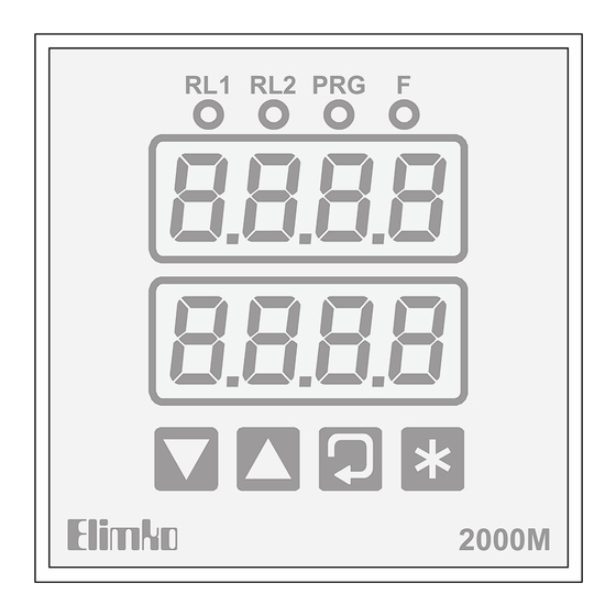
Display Type
2 x 4 digit 14 mm 7 segment led display
Thermocouple : (±0.5% of the reading value or ±1 C)
±1 digit max.
Pt-100 : (±0.5% of the reading value or ±1 C)
Accuracy
±1 digit max.
Analog Input: ±0.5% FS ±1 digit max.
Analog Digital Converter
16 bit
Digital Analog Converter
12 bit
Control Type
On/Off, PID
85-265 V AC / 85-375 V DC
Operating Voltage
20-60 V AC / 20-85 V DC
Power Consumption
4W (7 VA)
IP 65 Front Panel (NEMA 4X)
Encloser Ratings
IP 20 Rear Case
o
o
o
-10 C, +55 C (+14 F, +131 F)
Operating Temperature
(with no condensation or icing)
o
o
o
-25 C, +65 C (-13 F, +149 F)
Storage Temperature
( with no condensation or icing )
10.000.000 operations
(The relay life differs according to the usage
Relay Mechanical Life
configuration. When the relays are old, their contacts
could melt or burn
out.)
Relay Electrical Life
>1.000.000 operations (under 1/10 of load)
Memory
EEPROM (100.000 max. write-erase)
Weight
232 g
TYPE CODING
E-2000M-W-X-Y-Z
W
Relay/SSR
X
Analog Output
Y
0
No Relay
0
No Output
0
1
1 Relay
1
1 Analog Output
2
2 Relays
3
1 Pulse for SSR
4
1 Relay,1 Pulse for SSR
WIRING CONNECTION
24VDC
Operating
SSR
Voltage
Analog
Output
RL1
RL2
1
2
3
4
5
6
7
8
The labels on the sides of the controller identify the ordering code
(Type), serial number and wiring connections.
The controller options are also indicated on the wiring diagram.
The terminals 01 to 06 are electrically live. While the
instrument is powered, never touch to these terminals.
Before operating the controller, ensure that the controller
is correctly configured. Incorrect configuration could
result in damage to the process being controlled.
DIMENSIONS
96 mm
RL1 RL2 PRG
F
Elimko
2000M
E-2000M controller should be installed inside a
suitable grounded metal enclosure (panel). This must
prevent the live parts being accessible to human
hands and metal tools.
E-2000M controller does not include a power
switch. Therefore, the power supply to the
controller and power outputs must be wired through the proper fuse
or circuit breaker.
To minimize the pick-up of electrical noise, the wiring of low voltage
lines, particularly the sensor input should be routed away from the
high-current power cables. Where it is not possible, use shielded
cables with the shield grounded at both ends.
The cables used for powering the controller and the power outputs
must conform to the standarts IEC 60245 and IEC 60227.
+0.8
92x92mm
-0.0
min. 35 mm
RL1 Led
When lit, it indicates that RL1 output is active.
RL2 Led
When lit, it indicates that RL2 output is active.
PRG Led
When lit, it indicates that the controller is in the
configuration mode.
F Led
- When lit, it indicates that the controller is in
manual mode.
- F led will also flash when the auto-tuning
is in progress.
o
Upper
- While in normal operation, it displays the process value or
error message.
Display
o
- While in configuration pages, it displays the name of the
parameters.
Lower
- While in normal operation, it displays the control set point
Display
(Automatic mode) or manual output (Manual mode).
- While in configuration pages, it displays the parameter value.
Star
- When pressed together with button, password is asked
Button
for entering the configuration page.
- While in configuration pages, pressing this button reverts to
normal operation.
- While in normal operation, pressing this button for duration
3 seconds, toggles between automatic and manual mode. This
o
operation is disabled if the MPL parameter in page PRTC is
set to DSB or if the CNTL parameter in OCNF page is set other
o
than PID.
- While in normal operation, pressing this button acknowledges
the latched alarms if configured (AXLT = ON).
Enter
- When pressed together with button, password is asked for
Button
entering the configuration page.
- While in configuration pages, pressing this button selects the
next parameter.
- While in configuration pages, pressing this button for duration
2 seconds, returns to the top of the page.
- While in normal operation, pressing this button selects the
next parameter in operator page.
Up/
- While in normal operation, these buttons can be used to
edit the control set point (Automatic mode) or manual output
Down
Z
Operating Voltage
(Manual mode).
Buttons
0
85-265 V AC/85-375 V DC
- While in configuration, these buttons can be used to select
1
20-60 V AC/20-85 V DC
the configuration pages and to edit the parameters.
A1tp
or
A1SP or a2sp > 0
A2tp
Alarm State
1
RT
LO
mV
0
0
mA
Alarm State
1
TC
HI
0
0
Alarm State
1
9
10 11 12
LOD
0
0
Alarm State
1
HID
0
0
Alarm State
1
LOB
0
0
SP-ASP SP SP+ASP
Alarm State
6.5 mm
1
HIB
0
0 SP-ASP
OFF
Alarm function is cancelled when A1tp or A2TP parameters are off.
Shaded areas
show the
hysteresis.
AXHY
50 mm
PANEL MOUNTING
Cut a hole in the panel. (See the figure
for overall dimensions.)
Slide the controller into the cutout from
the front of the panel.
min. 10 mm
Fit the mounting clamps to the controller,
ensuring the lugs are located in their
slots.
Fasten the mounting clamps using the
retaining screws.
FRONT PANEL
Leds
RL1 RL2 PRG
F
140
Upper
Display
200
Lower
Display
Elimko
2000M
Enter
Button
Star
Up/Down
Buttons
Button
ALARM TYPES
EXPLANATIONS
A1SP or a2sp < 0
Alarm State
1
0
PV
PV
ASP
ASP
0
Alarm State
1
0
ASP
PV
ASP
0
Alarm State
1
0
SP
SP+ASP
PV
0
SP+ASP
SP
PV
AlarmState
1
0
SP
SP+ASP
PV
0
SP+ASP
SP
PV
Alarm State
1
0
PV
0
SP
PV
Alarm State
1
0
SP
SP+ASP
PV
0
SP
PV
Alarm State
When alarm state is
1
"1" the output (relay)
is active.
0
PV
0
ERROR MESSAGES
Message
Meaning
The connection of the sensor
Open
is broken.
The process value is below
Ufl
the sensor type-temperature
interval.
The process value is above
Ofl
the sensor type-temperature
interval.
The process value is
Nnnn
above the value that can
be displayed.
The process value is
Vvvv
below the value that can
be displayed.
INPUT TYPES and RANGES
TEMPERATURE SENSORS
Sensor Type
Standart
B
Type B
IEC584-1
Type E
E
IEC584-1
Type J
J
IEC584-1
Type K
K
IEC584-1
L
DIN43710
Type L
N
Type N
IEC584-1
R
IEC584-1
Type R
Type S
S
IEC584-1
Type T
T
IEC584-1
U
DIN43710
Type U
Pt-100
Pt
IEC751
LINEAR INPUTS
Type
0a20
Current
Current
4a20
Voltage
0v50
Voltage
00v1
Voltage
02v1
AUTO-TUNE
Auto-tuning matches the characteristics of the controller to the
process being controlled in order to obtain good control. Tuning
involves calculating and setting the values of the PID parameters.
The Auto-tuner works by switching the output on and off to induce an
oscillation in the process value. From the amplitude and period of
oscillations PID parameters are calculated.
Auto-tune can be performed at any time, but normally it is performed
only once during the initial commissioning of the process. However,
if the process under control subsequently becomes unstable
(because its characteristics have changed), you can re-tune again
for the new conditions.
In order to start Auto-tune process:
1- Set the CNTL parameter in OCNF page as PID.
2- Set the control set point to the value at which you will normally
operate the process. Consider also the process value may exceed
the control set point while in Auto-tuning.
3- Set the HYS parameter in TUNE page as 0. 1 (if DP=1) or 1 (if DP=0).
4- Set the AT parameter in TUNE page as ON to commence
Auto-tuning process. Press button to revert the normal operation.
The lower display and F led will flash to indicate that tuning is in
progress.
After a few cycles of oscillation the tuning is completed and the
calculated PID parameters PB, IT and DT are stored.
While the Auto-tuning in progress if AT parameter is set the OFF or
operating power of the controller is interrupted Auto-tune progress is
stopped and old PID values are retained.
MANUAL TUNING
If for any reason Auto-tuning gives unsatisfactory results, the controller
can be tuned manually. There are a number of standard methods for
manual tuning. The one described here is the Ziegler-Nichols method.
With the process at its normal running temperature:
Low
Alarm
Set the IT, DT and HYS parameters in TUNE page as 0.
1-
(Absolute)
2-
If OCR parameter in page OCNF is set to RL1, then set the CT
parameter 2.
High
Alarm
3-
Ignore the fact that the temperature may not settle precisely at the
(Absolute)
set point.
4-
If the temperature is stable, reduce the proportional band PB so that
Low
the temperature just starts to oscillate. If the temperature is already
Deviation
oscillating, increase the proportional band until it just stops oscillating.
(Relative)
Allow enough time between each adjustment for the loop to stabilize.
Make a note of the proportional band value (B) and the period of
oscillation (T).
High
Deviation
5-
Set the PB, IT and DT parameters values according to the calculations
(Relative)
given below.
Proportional
Type of
Band
Band
Control
Alarm
(PB)
(In)
P
2xB
PI
2.2xB
Band
Alarm
PID
1.7xB
(Out)
This controller complies with the European Low Voltage
Directive 73/23/EEC, by the application of safety standard
TS 2418 EN 61010-1. (Pollution degree 2)
This controller complies with the EMC Directive 89/336/EEC,
by the application of EMC standard TS EN 61326.
Remedy
Check the sensor and
the sensor connection.
Check the sensor and
the input type specified
by the INPT parameter.
Check the analog value
on the input terminal
and the scalar specified
by the Dp, Zero and span
parameters.
Temperature Range
o
o
( C)
( F)
,
,
60 1820
140
3308
,
840
,
1544
-200
-328
-200
,
-328
,
1120
1562
,
,
-200 1360
-328
2480
,
,
-200
900
-328
1652
-200 1300
,
-328
,
2372
-40 1760
,
104
,
3200
,
,
-40 1760
104
3200
,
,
-200
400
752
-328
,
,
-200
600
1112
-328
,
,
-328
1544
-200
840
Range
0-20 mA DC
4-20 mA DC
0-50 mV DC
0-1 V DC
0.2-1 V DC
Integral
Derivative
Time
Time
(IT)
(DT)
0
0
0.8xT
0
0.5xT
0.12xT
Advertisement
Table of Contents

Related Manuals for Elimko E-2000M


Summary of Contents for Elimko E-2000M
- Page 1 Cut a hole in the panel. (See the figure Nnnn Check the analog value above the value that can display. E-2000M indicating range is from -1999 to 9999 and is able to connect for overall dimensions.) on the input terminal be displayed.
- Page 2 00V2 Derivative Time 0 - 3600 / Manufacturer / Technical Support: Elimko Co. Ltd. 8. Cadde 68. Sokak No:16 06510 Emek - ANKARA / TURKEY Table 6 Sensor Break Case CNTL Phone:+ 90 312 212 64 50 Fax:+ 90 312 212 41 43 Hysteresis 0.
Need help?
Do you have a question about the E-2000M and is the answer not in the manual?
Questions and answers