
Subscribe to Our Youtube Channel
Related Manuals for Phcbi MBR-305GR Series


Summary of Contents for Phcbi MBR-305GR Series
- Page 1 Operating Instructions Blood Bank Refrigerator MBR-305GR Series Please read the operating instructions carefully before using this product, and keep the operating instructions for future use. See page 32 for all model numbers.
-
Page 3: Table Of Contents
CONTENTS INTRODUCTION P. 2 PRECAUTIONS FOR SAFE OPERATION P. 3 ENVIRONMENTAL CONDITIONS P. 7 REFRIGERATOR COMPONENTS Refrigerator unit P. 8 Control panel components P. 10 INSTALLATION SITE P. 11 INSTALLATION P. 12 START-UP OF UNIT P. 13 PLACING OF STORAGE ITEMS P. -
Page 4: Introduction
INTRODUCTION Read the operating instructions carefully before using the appliance and follow the instructions for safety operation. PHC Corporation never guarantees any safety if the appliance is used for any objects other than intended use or used by any procedures other than those mentioned in the operating instructions. ... -
Page 5: Precautions For Safe Operation
PRECAUTIONS FOR SAFE OPERATION It is imperative that the user complies with the operating instructions as it contains important safety advice. Items and procedures are described so that you can use this unit correctly and safely. If the precautions advised are followed, this will prevent possible injury to the user and any other person. - Page 6 PRECAUTIONS FOR SAFE OPERATION WARNING Do not use the unit outdoors. Current leakage or electric shock may result if the unit is exposed to rain water. The installation by Only qualified engineers or service personnel should install the unit. unqualified personnel may cause electric shock or fire. Install the unit on a sturdy floor and take an adequate precaution to prevent the unit from turning over.
- Page 7 PRECAUTIONS FOR SAFE OPERATION WARNING Ensure you do not inhale or consume medication or aerosols from around the unit at the time of maintenance. These may be harmful to your health. Never splash water directly onto the unit as this may cause electric shock or short circuit. Never put containers with liquid on the unit as this may cause electric shock or short circuit when the liquid is spilled.
- Page 8 PRECAUTIONS FOR SAFE OPERATION CAUTION This unit must be plugged into a dedicated circuit protected by branch circuit breaker. Use a dedicated power source as indicated on the rating label attached to the unit. multiple-tap may cause fire resulting from abnormal heating. Connect the power supply plug to the power source firmly after removing the dust on the plug.
-
Page 9: Environmental Conditions
ENVIRONMENTAL CONDITIONS This equipment is designed to be safe at least under the following conditions (based on the IEC 61010-1): Indoor use; Altitude up to 2000 m; Temperature 5 C to 40 Maximum relative humidity 80 % for temperature up to 31 C decreasing linearly to 50 % relative humidity at 40 ... -
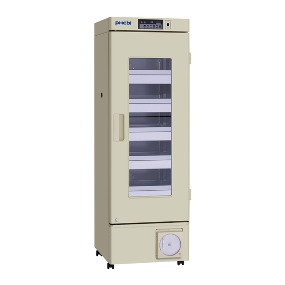
Page 10: Refrigerator Components
REFRIGERATOR COMPONENTS Refrigerator unit Power switch Glow starter [page 23] Light switch Florescent lamp [page 22] Door gasket Temperature recorder... - Page 11 REFRIGERATOR COMPONENTS 1. Door alarm switch: This switch detects the door status (open/close). The door check lamp is ON when the door is open and the alarm buzzer sounds with 2 minutes delay. [page 19] 2. Battery switch: ON-OFF switch for built-in battery for power failure alarm. Always turn on this switch when the refrigerator is operated to assure the power failure alarm.
-
Page 12: Control Panel Components
REFRIGERATOR COMPONENTS Control panel components 1. Door check indicator (DOOR): The red LED lamp is lit when the outer door is opened. 2 minutes after the door check indicator is ON, the alarm buzzer is activated to notice the door opening. [page 19] 2. -
Page 13: Installation Site
INSTALLATION SITE To operate this unit properly and to obtain maximum performance, install the unit in a location with the following conditions: A location not compliance with the following conditions may cause poor performance, failure or accident. A location not subjected to direct sunlight Do not install the unit under direct sunlight. -
Page 14: Installation
INSTALLATION 1. After unpackaging Remove all transportation packaging materials and tapes. Open the doors and ventilate the unit. If the outside panels are dirty, clean them with a diluted neutral dishwashing detergent. Undiluted detergent can damage the plastic components. For the dilution, refer to the instruction of the detergent. -
Page 15: Start-Up Of Unit
START-UP OF UNIT Follow the procedures for the initial and consequent operations of the unit. At the recovery from power failure, the operation is start-up automatically with temperature setting of 1. With the blood bank refrigerator empty, connect the power supply cord to the dedicated outlet with appropriate rating, and turn on the power switch. -
Page 16: Placing Of Storage Items
PLACING OF STORAGE ITEMS Do not disturb the air circulation in the chamber by the storage items. The disturbed air circulation can cause the freezing of storage items or degrade of temperature distribution in the chamber. Air intake vent Do not block the air intake by the storage items near the air intake vent. Care should be taken not to put any paper or plastic chips near the air intake vent. -
Page 17: Preparation Of Monitor Bottle
PREPARATION OF MONITOR BOTTLE Before start-up of the operation, fill the monitor bottles (upper and lower) with 10 % glycerol fluid or water of 200 mL by following the procedure below. 1. Remove top and bottom drawer. Recorder sensor 2. Remove the cover on the monitor bottle. (lower monitor bottle) Sensor for temp. -
Page 18: Display Of Chamber Temperature
DISPLAY OF CHAMBER TEMPERATURE The chamber temperature is set to 4 C at the factory. The temperature on the temperature display shows the temperature of sensor for temperature display attached to the monitor bottle (upper and lower). By pressing the temperature display changeover key, the displayed temperature is changed in sequence; upper temperature, lower temperature, and mean temperature of upper and lower temperature. -
Page 19: Remote Alarm Terminal
REMOTE ALARM TERMINAL The alarm status is noticed to a remote location when a remote alarm equipment (commercial item) is connected to the remote alarm terminal. It is recommended to install a remote alarm equipment (commercial item) when the blood bank refrigerator is installed in a desolate location so that an alarm status is noticed to an operator. -
Page 20: Calibration Of Sensor
CALIBRATION OF SENSOR The temperature on the temperature display shows the temperature of sensor for temperature display attached to the monitor bottle (upper and lower). Follow the procedure below when the calibration of the sensor for temperature display is necessary. 1. -
Page 21: Alarm Functions
ALARM FUNCTIONS This unit has the alarm functions shown below. Contact our sales representative or agent if the alarm status continues because there is a possibility of any failure. Alarms Situation Indication Alarm buzzer Remote alarm If the temperature of the upper High temp. -
Page 22: Self Diagnostic Functions
SELF DIAGNOSTIC FUNCTIONS This unit has the self diagnostic functions shown below. Contact our sales representative or agent if an error code (ex. E03) is displayed resulting from the self diagnostic. Self diagnostic Situation Indication Alarm buzzer Remote alarm Alarm indicator blinks. If the defrost sensor is E03 and chamber temp. -
Page 23: Routine Maintenance
ROUTINE MAINTENANCE WARNING Always disconnect the power supply to the unit prior to any repair or maintenance of the unit in order to prevent electric shock or injury. Ensure you do not inhale or consume medication or aerosols from around the unit at the time of maintenance. -
Page 24: Replacement Of Fluorescent Lamp
ROUTINE MAINTENANCE Replacement of fluorescent lamp Follow the procedure below when replacing a fluorescent lamp. The fluorescent lamp is located horizontally in the upper front of the chamber. [Page 8] 1. Turn off the light switch and power switch and then Socket disconnect the power supply plug. -
Page 25: Replacement Of Glow Starter
ROUTINE MAINTENANCE Replacement of glow starter The glow starter is located on the upper right of the unit. [Fig. 1] Glow starter 1. Turn off the light switch and power switch and then disconnect the power supply plug. 2. Remove the glow starter and install a new glow starter. (glow starter;... -
Page 26: Replacement Of Battery
REPLACEMENT OF BATTERY Replace the battery for power failure alarm every 3 years (when F-1 and chamber temperature is displayed alternately to ensure the alarm is operated in the event of power failure. Contact our sales representative or agent for the replacement of battery when F-1 and chamber temperature is displayed alternately. -
Page 27: Troubleshooting
TROUBLESHOOTING If the unit malfunctions, check out the following before calling for service. <Attention> If the malfunction is not eliminated after checking the following items or the malfunction is not shown in the table below, contact our sales representative or agent. Malfunction Check/Remedy If nothing operates even... -
Page 28: Disposal Of Unit
DISPOSAL OF UNIT WARNING If the unit is to be stored unused in an unsupervised area for an extended period ensure that children do not have access and doors cannot be closed completely. The disposal of the unit should be accomplished by appropriate personnel. Always remove doors to prevent accidents such as suffocation. - Page 29 DISPOSAL OF UNIT (English) Disposal of Old Equipment and Batteries Only for European Union and countries with recycling systems These symbols on the products, packaging, and/or accompanying documents mean that used electrical and electronic products and batteries must not be mixed with general household waste. For proper treatment, recovery and recycling of old products and used batteries, please take them to applicable collection points in accordance with your national legislation.
- Page 30 DISPOSAL OF UNIT (French) L’élimination des équipements et des batteries usagés Applicable uniquement dans les pays membres de l’Union européenne et les pays disposant de systèmes de recyclage. Apposé sur le produit lui-même, sur son emballage, ou figurant dans la documentation qui l’accompagne, ce pictogramme indique que les piles, appareils électriques et électroniques usagés, doivent être séparées des ordures ménagères.
- Page 31 DISPOSAL OF UNIT (Portuguese) Eliminação de Equipamentos Usados e Baterias Apenas para a União Europeia e países com sistemas de reciclagem Estes símbolos nos produtos, embalagens, e/ou documentos que os acompanham indicam que os produtos elétricos e eletrónicos e as baterias usados não podem ser misturados com os resíduos urbanos indiferenciados.
- Page 32 DISPOSAL OF UNIT (Dutch) Het ontdoen van oude apparatuur en batterijen. Enkel voor de Europese Unie en landen met recycle systemen. Deze symbolen op de producten, verpakkingen en/of begeleidende documenten betekenen dat gebruikte elektrische en elektronische producten en batterijen niet samen mogen worden weggegooid met de rest van het huishoudelijk afval.
-
Page 33: Specifications
SPECIFICATIONS Product name Blood Bank Refrigerator MBR-305GR External dimensions W600 mm x D680 mm x H1835 mm Internal dimensions W520 mm x D490 mm x H1150 mm Effective capacity 302 L Exterior Painted steel Interior Painted steel Outer door Painted steel, Provided with 2-layer glass window Inner door Acrylic resin, 2 doors Insulation... -
Page 34: Performance
PERFORMANCE Product name Blood Bank Refrigerator MBR-305GR Model number MBR-305GR-PA MBR-305GR-PK MBR-305GR-PR Storage temperature C (distribution; ±1.5 Usable ambient temperature C to 35 Noise level 41/41 dB (A scale) (50 Hz/60 Hz) Maximum pressure 1850 kPa Rated voltage AC 115 V AC 220 V AC 220 V Rated frequency... -
Page 35: Safety Check Sheet
CAUTION Please fill in this form before servicing. Hand over this form to the service engineer to keep for his and your safety. Safety check sheet 1. Unit contents: □ □ Risk of infection: □ □ Risk of toxicity: □ □... - Page 36 Original Operating Instructions 0123 Nijverheidsweg 120 4879 AZ Etten Leur, The Netherlands Printed in Japan 1-1-1 Sakada, Oizumi-machi, Ora-gun, Gunma 370-0596, Japan LDCL038300-0 S0418-0 © PHC Corporation 2018 2018.04.01...
Need help?
Do you have a question about the MBR-305GR Series and is the answer not in the manual?
Questions and answers