Advertisement
Quick Links
1
Summary Of
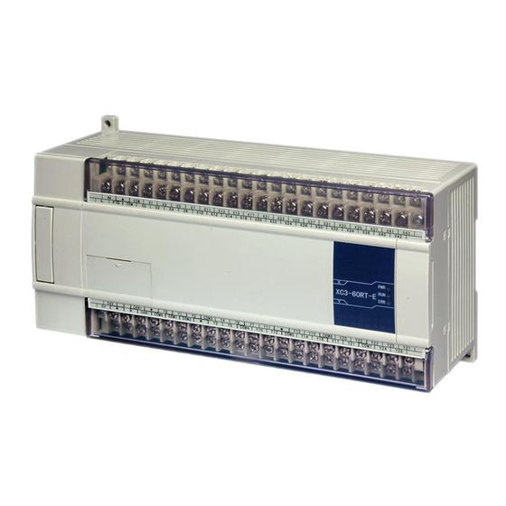
XC series PLC include diverse CPU units and expansions with powerful functions. This chapter
will mainly tell the main specifications, the whole products range, each part's description and
name template composing this four items.
1-1.Products Specifications
1-2.Model Composing and Model List
1-3.Each Part's Description
XC Series PLC
Advertisement


Need help?
Do you have a question about the XC Series and is the answer not in the manual?
Questions and answers