Table of Contents
Advertisement
I NSTALLATION, OPERATION and CAR E MAN UAL
W 1 6 4 N 9 2 2 1 W a t e r S t r e e t
PHONE:
262.251.3800
800.558.8744
.
.
.
P R I N T E D I N U
S
A
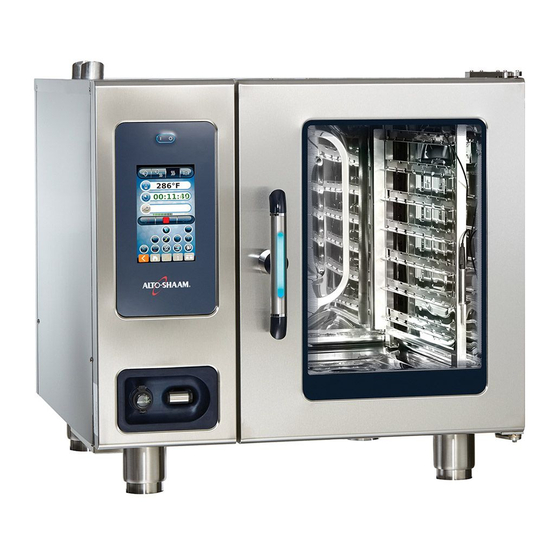
Gas Models:
6•10, 7•14,
10•10, 10•20,
12•18 & 20•20
Gas-Fired Combination
Oven/Steamer
United States & Canada Models
G
P . O . B o x 4 5 0
FAX: 262.251.7067 • 800.329.8744
.
.
./
262.251.1907
U
S
A
CANADA
G
M e n o m o n e e F a l l s , W i s c o n s i n 5 3 0 5 2 - 0 4 5 0
.
.
.
U
S
A
ONLY
INTERNATIONAL
®
WEBSITE:
www.alto-shaam.com
# 6 0 1 1 • 1 / 2 0 0 1
U . S . A .
Advertisement
Table of Contents


Need help?
Do you have a question about the COMBITHERM 6-10 and is the answer not in the manual?
Questions and answers