
Summary of Contents for GIRBAU FL Series
- Page 1 FL SERIES PNEUMATIC FOLDING MACHINE GIRBAU Crta de Manlleu, km.1 08500 VIC (Barcelona) .SPAIN 73100 Aix-Les-Bains - FRANCE Tél : 34 93 8861100 Fax : 34 93 8860785 girbau@girbau.es FL0610A www.girbau.com 5D00001/F...
- Page 3 PREAMBLE On my own behalf and on behalf of the GIRBAU company I would like to congratulate you for the purchase you have just made. I hope this product, the result of several years' experience, will give you complete satisfaction.
- Page 4 TECHNICAL MANUAL Part 1: General Points, Construction, Operation. Part 2: Electrical diagrams, delivered separately. Part 3: Automation, delivered separately. This technical manual gives detailed of all the Series FL folding machines, all options merged. Translation of original notice FL0610A...
-
Page 5: Table Of Contents
4.2 CROSS FOLDING UX2P.........................42 4.3 CROSS FOLDING UX3P.........................44 4.4 CROSS FOLDING MX2P ........................1 4.5 CROSS FOLDING MX3P ........................49 4.6 OPERATION OF FL SERIES FOLDING MACHINES ..............52 5 MAINTENANCE OPERATIONS ......................54 5.1 General maintenance ........................54 5.2 Air filter/regulator maintenance......................55 5.3 Troubleshooting ..........................57 6 SPARE PARTS .............................58... - Page 6 4M05516 FEEDER LU 3000 GIRBAU FLATWORK IRONER PC120 GAS ........113 4M05660 FEEDER LU 3300 GIRBAU FLATWORK IRONER PC120 GAS ........115 4M05661 FEEDER WITH BYPASS 1V/2V LU3000 GIRBAU FLATWORK IRONER PC120 GAS ..119 4M05663 FEEDER LU 3300 GIRBAU FLATWORK IRONER PC120 GAS ........115 4M05659 FEEDER WITH BYPASS 1V/2V LU3300 GIRBAU FLATWORK IRONER PC120 GAS ..121...
- Page 7 4M05265 OSCILLATING ARM LANE OF 825..................227 4M05266 OSCILLATING ARM LANE OF 750..................227 4M05267 OSCILLATING ARM LANE OF 875..................227 4M05401 GIRBAU LEFT COVER ASSEMBLY PS AND PSN8030.8033.8035 .........229 4M05402 GIRBAU RIGHT COVER ASSEMBLY PS AND PSN8030.8033.8035.......229 4M05309 LAPAUW RIGHT COVER ASSEMBLY ................231 4M05310 LAPAUW LEFT COVER ASSEMBLY.................231...
- Page 8 4M05416 RIGHT COVER ASSEMBLY CEFLEX 1200 GAS..............233 4M05417 LEFT COVER ASSEMBLY CEFLEX 1200 GAS ..............233 4M05419 LEFT COVER ASSEMBLY DUBIX CEFLEX 900 - 1200............235 4M05704 ROTATING CLAMP STACKER..................237 4M05558 CLAMP ..........................239 4M05474 PILROT DISCHARGE CONVEYOR (380-480V-50-60HZ)..........241 4M05835 PILROT DISCHARGE CONVEYOR (200-208V-50-60HZ)..........241 4M05836 PILROT DISCHARGE CONVEYOR (220-230V-50-60HZ)..........241 4M05705 ROTATING CLAMP STACKER BACK COVER ..............243 4E00478 ELECTRICAL BASE......................245...
-
Page 9: Ec Declaration Of Conformity
DECLARATION OF CONFORMITY FL0610A... - Page 10 FL0610A...
-
Page 11: Introduction
1 INTRODUCTION 1.1 WARNING Usage conditions: It is IMPERATIVE that all staff who have to work on this machine or maintain it (commissioning, maintenance, dismantling...) read and follow all the instructions contained in this notice, as well as those concerning control (electrical and pneumatic diagrams). -
Page 12: General Points
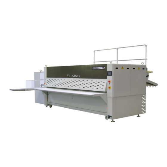
1.2 GENERAL POINTS The FL SERIES of folding machines has been specially designed for the fast, accurate folding of articles such as: Small items: cloths, pillowcases, mats. Large items: sheets, mattress covers, tablecloths, surgical sheets, fitted sheets. The machine integrates the latest technological advances in programmable, pneumatic and mechanical automatons. -
Page 13: Operation Pictograms
DANGER pictograms (yellow and black triangles): General danger Electrical danger Mechanical danger Danger of falling Mechanical maintenance DANGER area (yellow and black strip) 1.4 OPERATION PICTOGRAMS Emergency stop Use the touch screen Start Stop Reset FL0610A... - Page 14 Grease using a pump Set the selector to Start Set the selector to Stop and padlock it (padlock not provided) Open the air intake valve Shut the air intake valve and padlock it (padlock not provided) FL0610A...
-
Page 15: Technical Features
1.5 TECHNICAL FEATURES The technical features of the FL SERIES vary depending on the options ordered. Several folds can be made, depending on the model: 1, 2, or 3 primary folds in 1, 2 or 4 lanes using an air jet (the item comes out with... - Page 16 - Specific voltages and frequencies: - 208 Volts / 60 Hertz - 220-230 Volts / 50 Hertz - 220-230 Volts / 60 Hertz - 380-400 Volts / 60 Hertz - 440 Volts / 60 Hertz - 460 Volts / 60 Hertz - 480Volts / 60Hertz FL0610A...
- Page 17 FL0610A...
-
Page 18: Variants And Options
1.6 VARIANTS AND OPTIONS 1.6.1 PRIMARY FOLDING FOR FL-SMART-TYPE FOLDING MACHINE B-P: Feeder with by-pass (option) 1: Fold 1 blade position 1 air jet 1V, 2V, 4V 2: Fold 2 blade position 4 air jet 1V, 2V, 4V Bypas 2 folds Bypass fold fold... -
Page 19: Cross Folding Ux2P
1.6.3 CROSS FOLDING UX2P DISCHARGE ON TO SIDE TABLE 1st fold by mechanical blade 2: 2nd fold by mechanical blade and reversing conveyor Side table fold fold The operator picks up the cross-folded items on the discharge side table DISCHARGE WITH SINGLE ROTATING CLAMP STACKER 1st fold by mechanical blade 2nd fold by mechanical blade and reversing conveyor... -
Page 20: Cross Folding Ux3P
DISCHARGE WITH DOUBLE ROTATING CLAMP STACKER 1: 1st fold by mechanical blade 2: 2nd fold by mechanical blade and reversing conveyor 3: 3rd fold stacker) mechanical blade and rotating clamp fold fold fold The operator picks up the cross-folded and stacked items at the stacker discharge. 1.6.4 CROSS FOLDING UX3P DISCHARGE ON TO TABLE 1: 1st fold by mechanical blade... - Page 21 DISCHARGE WITH SINGLE FLAP STACKER 1: 1st fold by mechanical blade 2: 2nd fold by mechanical blade and reversing conveyor 3: 3rd cross fold by mechanical blade fold fold fold The operator picks up the cross-folded and stacked items at the stacker discharge. DISCHARGE WITH DOUBLE FLAP STACKER 1: 1st fold by mechanical blade 2: 2nd fold by mechanical blade and...
-
Page 22: Cross Folding Mx2P
1.6.5 CROSS FOLDING MX2P DISCHARGE ON TO SIDE TABLE In 1 lane 1 lane 1-lane operation: 1: 1st fold by mechanical blade 2: 2nd fold (if operating in 1 lane) by mechanical blade and reversing conveyor Side Side table table fold fold in 2 lanes... - Page 23 DISCHARGE WITH SINGLE ROTATING CLAMP STACKER 1-lane operation: in 1 lane 1: 1st fold by mechanical blade 2: 2nd fold by mechanical blade and reversing conveyor 3: 3rd fold (in the stacker) by mechanical blade and rotating clamp fold fold fold in 2 lanes 2-lane operation:...
- Page 24 DISCHARGE WITH DOUBLE ROTATING CLAMP STACKER in 1 lane 1-lane operation: 1st fold by mechanical blade 2nd fold by mechanical blade and reversing conveyor 3: 3rd fold (in the stacker) by mechanical blade and rotating clamp fold fold fold in 2 lanes 2-lane operation: 1st fold by mechanical blade 2: 3rd fold (in the stacker) by...
-
Page 25: Cross Folding Mx3P
1.6.6 CROSS FOLDING MX3P DISCHARGE ON TO SIDE TABLE 1-lane operation: in 1 lane 1st fold by mechanical blade 2nd fold by mechanical blade and reversing conveyor 3rd fold by mechanical blade Side table in 1 lane in 1 lane fold fold fold... - Page 26 DISCHARGE WITH SINGLE FLAP STACKER in 1 lane 1-lane operation: 1: 1st fold by mechanical blade 2: 2nd fold by mechanical blade and reversing conveyor 3: 3rd fold by mechanical blade fold fold fold in 2 lanes 2-lane operation: 1st fold by mechanical blade 2nd fold by mechanical blade fold fold...
- Page 27 DISCHARGE WITH DOUBLE FLAP STACKER 1-lane operation: 1: 1st fold by mechanical blade 2: 2nd fold by mechanical blade and reversing conveyor 3: 3rd fold by mechanical blade in 1 lane fold fold fold 2-lane operation: 1st fold by mechanical blade 2nd fold by mechanical blade in 2 lanes fold...
-
Page 28: Receiver (Option)
1.6.7 RECEIVER (Option) Upper conveyor Support FL0610A... -
Page 29: Handling Installation
2 HANDLING INSTALLATION The machine must only be handled by qualified personnel. During handling no one must place themselves below a load. 2.1 HANDLING Check that the lifting slings allow the weight of the machine to be lifted. TAKE CARE not to damage the covers. FL0610A... -
Page 30: Putting The Machine In Position
2.2 PUTTING THE MACHINE IN POSITION Preparation and positioning FL series folding machines: see following pages. The floor must be horizontal and capable of bearing the weight of the machine. Note: Carry out these operations strictly in order. - Screw up the four adjustment jacks so that the machine rests on its four transport wheels. - Page 31 If the machine has been sent in plastic film, carry out the following operations: - Raise the primary fold discharge table. - Slightly loosen the screw and pivot the table. - Add the bottom screw, allowing the table to remain horizontal. FL0610A...
- Page 32 - Raise the feeder conveyor (Feeder) Go to stage 8 If the machine has been sent in a wooden crate, carry out the following operations: Machine folded up Turn the OPG FL0610A...
- Page 33 Pivot the service bridge assembly Loosen the screw slightly FL0610A...
- Page 34 Make it pivot Replace the fixing screw Dismantle the flap so you can adjust the service bridge horizontally FL0610A...
- Page 35 Raise the feeder. FL0610A...
- Page 36 - Place the folding machine in the best possible position behind the ironer. The folding machine and the ironer must be perfectly aligned. The folding machine's roller must be level and parallel with the ironer bed discharge. - Unscrew the four adjustment jacks enough to lift the four transport wheels off the ground (resting on the folding machine).
- Page 37 CHECKING AND LEVELLING Check that the 2 lower crossbeams are level. Check that the folding machine's 2 cabinets are level. Check the positioning of the feeder roller with respect to the ironer bed and make sure it is level. Make sure the service bridge is level. Once the cylinders have been adjusted, lock them with their lock nuts.
- Page 38 CONNECTION TO SUPPLIES: Connection to the air supply The machine is equipped with an air treatment unit: Filter/Regulator, see chapter 5 Maintenance operations. The customer must provide the air supply to the machine's on/off valve. This air must be dry and dust-free. Pipes of minimum diameter 15/ 21 (1/2 inch) must be used to supply the machine.
- Page 39 Connection to the power supply: The electrical installation of the machine must be carried out by qualified, authorised staff . - Make sure that the power supply is correct and that the power of your installation is sufficient before connecting the machine. The power cable must be protected at the head of the line.
-
Page 40: Safety
3 SAFETY 3.1 GENERAL POINTS Note: Read and comply with chapter 1 Warning. Machine EMERGENCY STOP: - Press the Emergency stop button: When there is an emergency stop, all movements are stopped. The machine must be started up again by the operator responsible. He/she will press the reset button after making sure there is no further danger. -
Page 41: Intervention During Operation
3.3 INTERVENTION DURING OPERATION It is strictly forbidden to intervene during operation. Before intervening and after the machine has completely stopped, it is essential to: - Set the main switch to OFF and padlock it Padlock not provided - Close the air intake valve and padlock it. Padlock not provided When various movable covers on the machine are opened, it stops. -
Page 42: Positioning Of Emergency Stops And Safety Contacts
3.4 POSITIONING OF EMERGENCY STOPS AND SAFETY CONTACTS NEVER REMOVE OR TRY TO ALTER SAFETY ELEMENTS Emergency Emergency stop stop Ref: 13-0787 Ref: 13-0787 Safety sensor Ref: 13-0454 Safety sensor Ref: 13-0454 FL0610A... - Page 43 Protective grille safety sensor Ref: 13-0457 REP7 FL0610A...
-
Page 44: Principle And Operation
4.1 PRINCIPLE Never try to pick up an item that is jammed in the machine. The FL SERIES can deal with large or small items equally well. - The item arrives from the ironer. - It is received on a conveyor called a "feeder". - Page 45 4.2 CROSS FOLDING UX2P DISCHARGE ON TO SIDE TABLE 1: 1st fold by mechanical blade 2: 2nd fold by mechanical blade and reversing conveyor Side table fold fold The operator picks up the cross-folded items on the discharge side table DISCHARGE WITH SINGLE ROTATING CLAMP STACKER 1: 1st fold by mechanical blade 2: 2nd fold by mechanical blade and...
-
Page 46: Cross Folding Ux3P
DISCHARGE WITH DOUBLE ROTATING CLAMP STACKER 1st fold by mechanical blade 2nd fold by mechanical blade and reversing conveyor 3rd fold (in the stacker) by mechanical blade and rotating clamp fold fold fold The operator picks up the cross-folded and stacked items at the stacker discharge. 4.3 CROSS FOLDING UX3P DISCHARGE ON TO TABLE Side... - Page 47 DISCHARGE WITH SINGLE FLAP STACKER 1: 1st fold by mechanical blade 2: 2nd fold by mechanical blade and reversing conveyor 3: 3rd cross fold by mechanical blade fold fold fold The operator picks up the cross-folded and stacked items at the stacker discharge. DISCHARGE WITH DOUBLE FLAP STACKER 1: 1st fold by mechanical blade 2: 2nd fold by mechanical blade and...
-
Page 48: Cross Folding Mx2P
4.4 CROSS FOLDING MX2P DISCHARGE ON TO SIDE TABLE in 1 lane 1-lane operation: 1st fold by mechanical blade 2: 2nd fold (if operating in 1 lane) by mechanical blade and reversing conveyor Side table fold fold in 2 lanes 2-lane operation: 1: 1st fold by mechanical blade Side... - Page 49 DISCHARGE WITH SINGLE ROTATING CLAMP STACKER in 1 lane 1-lane operation: 1st fold by mechanical blade 2nd fold by mechanical blade and reversing conveyor 3rd fold (in the stacker) by mechanical blade and rotating clamp fold fold fold in 2 lanes 2-lane operation: 1st fold by mechanical blade 3rd fold (in the stacker) by mechanical...
- Page 50 DISCHARGE WITH DOUBLE ROTATING CLAMP STACKER in 1 lane 1-lane operation: 1st fold by mechanical blade 2nd fold by mechanical blade and reversing conveyor 3rd fold (in the stacker) by mechanical blade and rotating clamp fold fold fold in 2 lanes 2-lane operation: 1st fold by mechanical blade 3rd fold (in the stacker) by mechanical...
-
Page 51: Cross Folding Mx3P
4.5 CROSS FOLDING MX3P DISCHARGE ON TO SIDE TABLE 1-lane operation: in 1 lane 1st fold by mechanical blade 2nd fold by mechanical blade and reversing conveyor 3rd fold by mechanical blade Side table fold fold fold in 2 lanes 2-lane operation: 1st fold by mechanical blade 2nd fold by mechanical blade... - Page 52 DISCHARGE WITH SINGLE FLAP STACKER in 1 lane 1-lane operation: 1st fold by mechanical blade 2nd fold by mechanical blade and reversing conveyor 3rd fold by mechanical blade in 2 lanes 2-lane operation: 1st fold by mechanical blade 2nd fold by mechanical blade fold fold The operator picks up the cross-folded and stacked items at the stacker discharge.
- Page 53 DISCHARGE WITH DOUBLE FLAP STACKER 1-lane operation: 1st fold by mechanical blade 2nd fold by mechanical blade and reversing conveyor 3rd fold by mechanical blade in 1 lane fold fold fold 2-lane operation: 1st fold by mechanical blade 2nd fold by mechanical blade in 2 lanes fold fold...
-
Page 54: Operation Of Fl Series Folding Machines
4.6 OPERATION OF FL SERIES FOLDING MACHINES Make sure that no-one has their hands in the machine. Check that all covers are in place and that no-one is working on or under the machine. Before starting the machine, check: - The direction the motors are turning, - The air pressure, which must be 6 bars. - Page 55 - Press the Stop button. - Set the main switch to OFF. - Close the general compressed air valve. FL0610A...
-
Page 56: Maintenance Operations
5 MAINTENANCE OPERATIONS - Before any intervention on the machine: - Set the main switch to the OFF position and padlock it. - Close the connection valve to the compressed air supply and padlock it. 5.1 General maintenance Every day or every 10 hours: - Visually check the machine. -
Page 57: Air Filter/Regulator Maintenance
5.2 Air filter/regulator maintenance GENERAL USAGE CONDITIONS: Control fluid : Air I.S.O.8573, minimum class 3.5.3. Ambient temperature : -20°C to 50°C Maximum supply pressure : 10 bars. FILTER AND REGULATOR-FILTER equipped with a safety device preventing dismantling under pressure. Assembly Dismantling Clean the tank with soapy water only. - Page 58 A key locking system is possible using a padlockable cap. PADLOCKABLE VALVE: When carrying out manual actions on the machine, always lock the valve with at least one padlock so that no-one can turn the pressure on during a manual action. CLOG-FREE SILENCER For safety reasons, never replace the clog-free silencer with a device using a technology that means it could clog up.
-
Page 59: Troubleshooting
5.3 Troubleshooting MALFUNCTIONS CAUSES SOLUTIONS Reset the circuit breaker concerned One of the motor-circuit brakers The folding machine will not start. and check why it was set off. or a safety device is engaged. Remove the emergency stops. Check that the movable covers are properly closed. -
Page 60: Spare Parts
6 SPARE PARTS 6.1 FL-SMART - FL-KING BASIC EMERGENCY KIT 5M01127-04-10-U Reference Description 10-0820/24 Clutch 24V 14-0263 Cylinder Iso D25*25 14-0264 Cylinder Iso D25*50 14-1537 Distributor MEBH 5/2-1/8-I-b 14-0184 Complete blowing distributor 15-0034 Cell 15-0186 2D00428/24 Complete electromagnetic brake 4M02900 OPG with connector 14-1720/sav Sensor... -
Page 61: Fl-Smart - Fl-King Industrial Maintenance Kit
6.3 FL-SMART - FL-KING INDUSTRIAL MAINTENANCE KIT 5M01127-04-10-I Reference Description 10-0820/24 Clutch 24V 14-0263 Cylinder Iso D25*25 14-0264 Cylinder Iso D25*50 14-1537 Distributor MEBH 5/2-1/8-I-b 14-0184 Complete blowing distributor 15-0034 Cell 15-0186 2D00428/24 Complete electromagnetic brake 4M02900 OPG with connector 14-1720/sav Sensor 10-0200... -
Page 62: List Of Straps
Type 2C01961 42 to 48 Antistatic cream cotton strap LA50 LG7050 2C01962 42 to 48 Girbau PC120 flatwork ironer Gas Antistatic cream cotton strap LA50 LG7600 2C01963 42 to 48 Bypass option Antistatic cream cotton strap LA50 LG5850 If UX2P or UX3P... - Page 63 2C01961 42 to 48 Antistatic cream cotton strap LA50 LG7050 2C01962 42 to 48 Girbau PC120 flatwork ironer Gas Antistatic cream cotton strap LA50 LG7600 2C01963 42 to 48 Bypass option Antistatic cream cotton strap LA50 LG5850 If UX2P or UX3P...
- Page 64 - Cross fold section straps Discharge on table UX2P Pos. Type 2C01853 Grey spur strap LA60/LG530 2C01854 Grey spur strap LA60/LG550 2C01729 PVC strap LA60/LG910 PVC strap LA50/LG Discharge on 1 Stacker (ROT. STA.) UX2P Pos. Type 2C01853 Grey spur strap LA60/LG530 2C01854 Grey spur strap LA60/LG550 2C01729...
- Page 65 Discharge on 2 Stackers (PIL ROT) UX2P Pos. Type 2C01853 Grey spur strap LA60/LG530 2C01854 Grey spur strap LA60/LG550 2C01729 PVC strap LA60/LG910 PVC strap LA50/LG Discharge on flap stacker UX3P Pos. Type 2C01853 Grey spur strap LA60/LG530 2C01854 Grey spur strap LA60/LG550 2C01729 PVC strap LA60/LG910 2C01892...
- Page 66 Discharge on table UX3P Pos. Type 2C01853 Grey spur strap LA60/LG530 2C01854 Grey spur strap LA60/LG550 2C01729 PVC strap LA60/LG910 2C01892 PVC strap LA50/LG3440 2C01890 Grey spur strap LA 50 LG825 2C01891 Grey spur strap LA 50 LG1290 - Cross fold section straps MX2P Discharge on to table Pos.
- Page 67 Discharge on 1 Stacker (ROT. STA.) MX2P Pos. Type Qty. 2C01853 Grey spur strap LA60/LG530 2C01854 Grey spur strap LA60/LG550 2C01729 PVC strap LA60/LG910 2C01950 LU 3000 PVC strap LA50/LG 8520 2C01951 LU 3300 PVC strap LA50/LG 8670 2C01952 LU 3500 PVC strap LA50/LG 8770 Discharge on 2 Stackers (ROT.
- Page 68 Discharge on side table MX3P Pos. Type 2C01853 Grey spur strap LA60/LG530 2C01854 Grey spur strap LA60/LG550 2C01729 PVC strap LA60/LG910 2C01903 LU 3000 PVC strap LA50/LG4925 2C01904 LU 3300 PVC strap LA50/LG5080 2C01905 LU 3500 PVC strap LA50/LG5175 2C01890 Grey spur strap LA50/LG825 2C01891 Grey spur strap LA50/LG1290...
- Page 69 4M05660 Feeder LU 3300 Girbau flatwork ironer PC120 gas............115 4M05661 Feeder LU 3500 Girbau flatwork ironer PC120 gas............115 4M05663 Feeder with bypass 1V/2V LU3000 Girbau flatwork ironer PC120 gas ......119 4M05659 Feeder with bypass 1V/2V LU3300 Girbau flatwork ironer PC120 gas ......121 4M05662 Feeder with bypass 1V/2V LU3500 Girbau flatwork ironer PC120 gas ......123...
- Page 70 4M05160 1st primary fold 2 lanes LU 3300 ..................143 4M05161 1st primary fold 2 lanes LU 3500 ..................143 4M05162 1st primary fold 4 lanes LU 3000 ..................145 4M05163 1st primary fold 4 lanes LU 3300 ..................145 4M05164 1st primary fold 4 lanes LU 3500 ..................145 4M05186 2nd primary fold 2 lanes LU 3000..................147 4M05187 2nd primary fold 2 lanes LU 3300..................147 4M05188 2nd primary fold 2 lanes LU 3500..................147...
- Page 71 4M05265 Oscillating arm lane of 825 ....................227 4M05266 Oscillating arm lane of 750 ....................227 4M05267 Oscillating arm lane of 875 ....................227 4M05401 Girbau left cover assembly PS and PSN8030.8033.8035 ..........229 4M05402 Girbau right cover assembly PS and PSN8030.8033.8035..........229 4M05309 Lapauw right cover assembly .....................231 4M05310 Lapauw left cover assembly ....................231...
- Page 72 FL0610F...
-
Page 73: Description (Exploded Views)
8 DESCRIPTION (EXPLODED VIEWS) FL0610A... - Page 74 KIT 09 -0004F KIT 09 -0102F FL0610F...
-
Page 75: Kit 09-0004F Supplementary Pressure Kit
KIT 09-0004F SUPPLEMENTARY PRESSURE KIT Reference Qty Description 14-0100 Manifold Regulator 33dm3/s 3/8" 14-0144 Pressure gauge D43 0-6b midi 14-0143 Excellon Quicklamp 72 14-0406 Straight connector 06-1/4" KIT 09-0102F RECEIVER AND RECEIVER BYPASS KIT Pos. Reference Description 14-0294 Cylinder Iso D16*50, shock absorber Cylinder 14-0429 Elbow connector 06-M5... - Page 76 KIT 09-0118E FL0610F...
-
Page 77: Kit 09-0118E Flap Indicator Kit
KIT 09-0118E FLAP INDICATOR KIT Pos. Reference Qty Description 14-1297 Cylinder Iso D32*80 Cylinder Banjo flow regulator 06-1/8" assembly 14-0366 Front hinge joint D25/32 14-1297 Cylinder Iso D32*80 Cylinder Banjo flow regulator 06-1/8" assembly 14-0362 Female front clevis D25/32 FL0610A... - Page 78 KIT 09-0124F KIT 09-0125F FL0610F...
-
Page 79: Kit 09-0124F Blowing Valve Kit - 4 Lanes
KIT 09-0124F BLOWING VALVE KIT - 4 LANES Pos. Reference Description External nut straight connectorR3/8"-14 14-0426 Elbow connector 10-1/4" Distributor assembly 14-0421 Elbow connector 04-1/8" 14-0184 14-1456 Dist. Iso 01-2/2 mono-24Vcc-ext. 2D-01652 Special connector 2P02834 Special base External nut straight connectorR3/8"-14 Elbow connector 10-1/4"... - Page 80 KIT 09-0126F KIT 09-0127G FL0610F...
-
Page 81: Kit 09-0126F Feeder Bypass Kit
KIT 09-0126F FEEDER BYPASS KIT Reference Description 14-0264 Cylinder Iso D25*50 Cylinder assembly 14-0107 Banjo flow regulator 06-1/8" 14-0366 Front hinge joint D25/32 KIT 09-0127G UPPER CROSS CONVEYOR CONNECTION BYPASS KIT Pos. Reference Description 14-0675 Cylinder Iso D32*100 14-0107 Banjo flow regulator 06-1/8" Cylinder assembly 14-0368 Male joint D32... - Page 82 KIT 09-0134F KIT 09-0135F FL0610A...
-
Page 83: Kit 09-0134F Blowing Valve Kit - 2 Lanes
KIT 09-0134F BLOWING VALVE KIT - 2 LANES Pos. Reference Description 2P02834 Special base 2D01652 Special connector Distributor 14-1456 Dist. Iso 01-5/2 mono-24Vcc-ext assembly 14-0421 Elbow connector 04-1/8" 14-0184 14-0426 Elbow connector 10-1/4" Straight connector with external nut R3/8" - 2P02834 Special base 2D01652... - Page 84 KIT 09-0137F KIT 09-0138F FL0610A...
-
Page 85: Kit 09-0137F Retractable Strap Lifting Guide Kit Fold2
KIT 09-0137F RETRACTABLE STRAP LIFTING GUIDE KIT FOLD2 Pos. Description 14-0383 Cylinder Iso D25*25 Cylinder 14-0422 Elbow connector 06-1/8" assembly 14-0366 Front hinge joint D25/32 Elbow MF 1/8" 14-0569 Silent flow regulator 1/8" 14-0422 Elbow connector 06-1/8" Bulk 14-0404 Straight connector 06-1/8" Elbow MF 06 14-0447 "Y"...
Need help?
Do you have a question about the FL Series and is the answer not in the manual?
Questions and answers