Table of Contents
Advertisement
Advertisement
Table of Contents

Related Manuals for Siemens 6ES7 972-4AA02-0XA0


Summary of Contents for Siemens 6ES7 972-4AA02-0XA0
- Page 1 Artisan Technology Group is your source for quality new and certified-used/pre-owned equipment SERVICE CENTER REPAIRS WE BUY USED EQUIPMENT • FAST SHIPPING AND DELIVERY Experienced engineers and technicians on staff Sell your excess, underutilized, and idle used equipment at our full-service, in-house repair center We also offer credit for buy-backs and trade-ins •...
- Page 2 User´s Guide Power Rail Booster Version 12/2005 Power Rail Booster User’s Guide Version 12/2005 Copyright © Siemens AG 2005 All rights reserved. 6ES7 972-4AA02-0XA0 Page 1 of 49 Artisan Technology Group - Quality Instrumentation ... Guaranteed | (888) 88-SOURCE | www.artisantg.com...
- Page 3 Suggestions for improvement are welcomed. Copyright Copyright © Siemens AG 2005. All rights reserved. The reproduction, transmission or use of this document or its content is not permitted without express written authority.
- Page 4 Validity of this manual The manual is designed for use with the Power Rail Booster for PROFIBUS-DP with the order No. 6ES7 972-4AA02-0XA0. This manual describes components that are valid at the time of publishing. We reserve the right to include current product information on any new components and components with a newer release level.
- Page 5 Yes / yes, product release 3 Signalling contact / diagnostics Yes / no and above 3 Copyright © Siemens AG 2005 All rights reserved. 6ES7 972-4AA02-0XA0 Page 4 of 49 Artisan Technology Group - Quality Instrumentation ... Guaranteed | (888) 88-SOURCE | www.artisantg.com...
-
Page 6: Table Of Contents
................ 31 ONNECTING THE OWER AIL INTERFACE 6.3.2.4 PROFIBUS ................ 31 ONNECTING THE INTERFACE Copyright © Siemens AG 2005 All rights reserved. 6ES7 972-4AA02-0XA0 Page 5 of 49 Artisan Technology Group - Quality Instrumentation ... Guaranteed | (888) 88-SOURCE | www.artisantg.com... - Page 7 IAGNOSTICS STANDARDS AND CERTIFICATIONS ................. 43 GLOSSARY........................... 45 LIST OF FIGURES ........................ 49 Copyright © Siemens AG 2005 All rights reserved. 6ES7 972-4AA02-0XA0 Page 6 of 49 Artisan Technology Group - Quality Instrumentation ... Guaranteed | (888) 88-SOURCE | www.artisantg.com...
-
Page 8: General Remarks
Provides important information about the product, the handling of the product or about a specific part of the documentation to which attention needs to be called. Copyright © Siemens AG 2005 All rights reserved. 6ES7 972-4AA02-0XA0 Page 7 of 49... - Page 9 Use as The device may be used only for the applications described in this prescribed Guide and only in conjunction with non-Siemens devices and components recommended or authorized by Siemens. Proper transport, storage and installation as well as careful operation and maintenance of the device are prerequisites for problem-free and safe operation.
-
Page 10: Introduction
Traversing tracks. It is also generally recommended that the Power Rail Booster be used for cost- efficient, safe and reliable PROFIBUS transmissions via contact rails or cables. Copyright © Siemens AG 2005 All rights reserved. 6ES7 972-4AA02-0XA0 Page 9 of 49... - Page 11 Version 12/2005 The following illustration shows a sample application. Fig. 1: Sample application of the Power Rail Booster Copyright © Siemens AG 2005 All rights reserved. 6ES7 972-4AA02-0XA0 Page 10 of 49 Artisan Technology Group - Quality Instrumentation ... Guaranteed | (888) 88-SOURCE | www.artisantg.com...
-
Page 12: General Functions
The PRBs recognize any changes in the transmission speed during operation and reconfigure themselves accordingly. Brief transmission problems may occur at the moment of switch-over. Copyright © Siemens AG 2005 All rights reserved. 6ES7 972-4AA02-0XA0 Page 11 of 49... -
Page 13: Led Test On Activating The Voltage Supply
= “ON” corresponds to 2 • LED „DP“ = „ON“ corresponds to 2 Copyright © Siemens AG 2005 All rights reserved. 6ES7 972-4AA02-0XA0 Page 12 of 49 Artisan Technology Group - Quality Instrumentation ... Guaranteed | (888) 88-SOURCE | www.artisantg.com... -
Page 14: Controlling The "Is-Master" Signal
For a more detailed description of the diagnostics message frame refer to Chapter 7.2 "Diagnostics message frame". Copyright © Siemens AG 2005 All rights reserved. 6ES7 972-4AA02-0XA0 Page 13 of 49 Artisan Technology Group - Quality Instrumentation ... Guaranteed | (888) 88-SOURCE | www.artisantg.com... -
Page 15: Network Topologies For Contact Rail Systems
This can be done using rail sections (see Chapter 4.4 „Rail sections“). Fig. 3: Block diagram of a DP master segment with two PRB segments Copyright © Siemens AG 2005 All rights reserved. 6ES7 972-4AA02-0XA0 Page 14 of 49... -
Page 16: Introduction
"IS-Master" signal on both PRBs. To do this, you must set on both PRBs DIP switches DIP-7 and DIP-8 to "ON". Fig. 5: Example of a point-to-point connection Copyright © Siemens AG 2005 All rights reserved. 6ES7 972-4AA02-0XA0 Page 15 of 49... -
Page 17: Line Topology
The star structure is permissible on no more than two levels (paths and branches. Fig. 7: Example of star topology Copyright © Siemens AG 2005 All rights reserved. 6ES7 972-4AA02-0XA0 Page 16 of 49 Artisan Technology Group - Quality Instrumentation ... Guaranteed | (888) 88-SOURCE | www.artisantg.com... -
Page 18: Closed Ring Circuits
When using systems with closed loops, it is recommended to establish a low- resistance connection to ground with the steel construction parallel to the contact rail. Fig. 8: Example of a closed loop Copyright © Siemens AG 2005 All rights reserved. 6ES7 972-4AA02-0XA0 Page 17 of 49... -
Page 19: Rail Sections
Note When installing rail sections, care must be taken when aligning the junctions in order to avoid bounce. Copyright © Siemens AG 2005 All rights reserved. 6ES7 972-4AA02-0XA0 Page 18 of 49 Artisan Technology Group - Quality Instrumentation ... Guaranteed | (888) 88-SOURCE | www.artisantg.com... -
Page 20: Configuration
DP master segment with a stationary PRB. Copyright © Siemens AG 2005 All rights reserved. 6ES7 972-4AA02-0XA0 Page 19 of 49 Artisan Technology Group - Quality Instrumentation ... Guaranteed | (888) 88-SOURCE | www.artisantg.com... - Page 21 The modifications must once again be briefly discussed with the electricians. Copyright © Siemens AG 2005 All rights reserved. 6ES7 972-4AA02-0XA0 Page 20 of 49...
-
Page 22: Configuration With The „Prb Checker
“PRB Checker” software tool for easy, fast and reliable calculation of the lengths of the individual PRB segments. This tool can be obtained through Siemens Customer Support under the ID: 13884116 for downloading over the Internet. - Page 23 Power Rail Segment Controller that is connected to a PRB segment as an additional vehicle. This is due to the Power Rail Segment Controller's input capacitance. Copyright © Siemens AG 2005 All rights reserved. 6ES7 972-4AA02-0XA0 Page 22 of 49...
-
Page 24: Configuration Of The Bus Parameters
Number of OLMs = Number of PRBs connected in series The delay level is: T (in Tbit) = 2 *Number of OLMs in series * 6Tbit Copyright © Siemens AG 2005 All rights reserved. 6ES7 972-4AA02-0XA0 Page 23 of 49... -
Page 25: Adapting The„Retry Limit" Parameter
PRB involved in communication must be maximum of 100 ohms. In this connection, you must take into account all the transition resistors of Copyright © Siemens AG 2005 All rights reserved. 6ES7 972-4AA02-0XA0 Page 24 of 49... -
Page 26: Preferred Arrangement Of The Contact Conductors
Power Rail above the other contact conductors and slightly offset the rail sections Fig. 15: Preferred arrangement of the contact conductors Copyright © Siemens AG 2005 All rights reserved. 6ES7 972-4AA02-0XA0 Page 25 of 49 Artisan Technology Group - Quality Instrumentation ... Guaranteed | (888) 88-SOURCE | www.artisantg.com... -
Page 27: Preferred Arrangement Of The Wires In Cables
Too little pressure and poorly adjusted contact rail junctions result in bounce and thus lead to interruptions in data transmission. Copyright © Siemens AG 2005 All rights reserved. 6ES7 972-4AA02-0XA0 Page 26 of 49... -
Page 28: Commissioning
Take the necessary measures and/or install suitable elements to ensure that all interfaces are protected against lightning strikes affecting the plant, whether indoors or outdoors. Copyright © Siemens AG 2005 All rights reserved. 6ES7 972-4AA02-0XA0 Page 27 of 49 Artisan Technology Group - Quality Instrumentation ... Guaranteed | (888) 88-SOURCE | www.artisantg.com... -
Page 29: General Information Regarding Commissioning
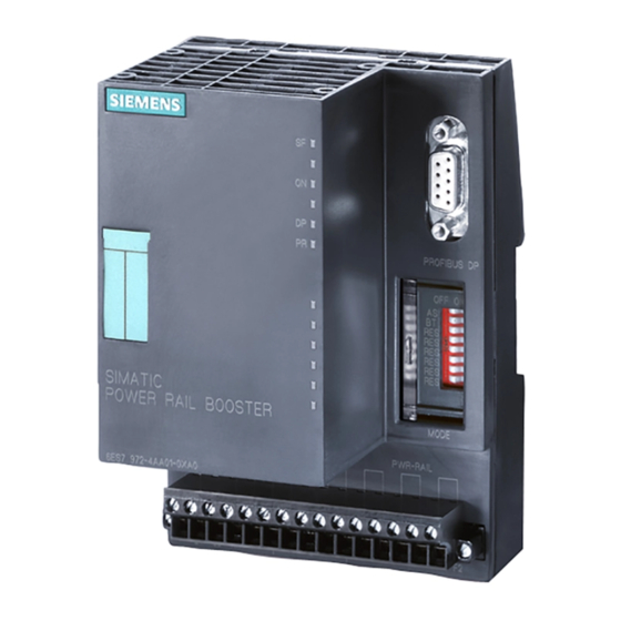
Connect the Power Rail Connect the RS 485 bus cable with preassembled bus connector Fig. 17: Front view of the Power Rail Booster. Copyright © Siemens AG 2005 All rights reserved. 6ES7 972-4AA02-0XA0 Page 28 of 49 Artisan Technology Group - Quality Instrumentation ... Guaranteed | (888) 88-SOURCE | www.artisantg.com... -
Page 30: Installation
The PRB is removed by pulling the locking lever downward. With the lever held down, the PRB can be simply lifted off the top hat rail. Fig. 18: Installing a PRB on a standard top hat rail Copyright © Siemens AG 2005 All rights reserved. 6ES7 972-4AA02-0XA0 Page 29 of 49... -
Page 31: Interfaces And Connector Pin Assignment
Sleeves See DIN 46228 Fig. 20: Wiring guidelines for the interfaces of the Power Rail Booster Copyright © Siemens AG 2005 All rights reserved. 6ES7 972-4AA02-0XA0 Page 30 of 49 Artisan Technology Group - Quality Instrumentation ... Guaranteed | (888) 88-SOURCE | www.artisantg.com... -
Page 32: Connecting The Power Rail Interface
The operating voltage is connected via the 15-pin terminal block on the front of the PRB. The connection is protected against polarity reversal. Pins 1-2 and pins 3-4 are jumpered internally. Copyright © Siemens AG 2005 All rights reserved. 6ES7 972-4AA02-0XA0 Page 31 of 49... -
Page 33: Connecting The Signalling Contacts
When the PRB is deenergized, terminals 12 and 14 are separated from terminal 6.3.2.7 Connection scheme for wiring PRB Fig. 25: Connection scheme PRB Copyright © Siemens AG 2005 All rights reserved. 6ES7 972-4AA02-0XA0 Page 32 of 49 Artisan Technology Group - Quality Instrumentation ... Guaranteed | (888) 88-SOURCE | www.artisantg.com... -
Page 34: Determining The Transfer Resistance Of Collectors
The following applies to the resistance ( R ) measured via both double sliding contacts: R ≤ 100 ohms Copyright © Siemens AG 2005 All rights reserved. 6ES7 972-4AA02-0XA0 Page 33 of 49 Artisan Technology Group - Quality Instrumentation ... Guaranteed | (888) 88-SOURCE | www.artisantg.com... -
Page 35: Led Display And Troubleshooting
Reserve Not currently used Fig. 28: Possible LED displays and their causes Copyright © Siemens AG 2005 All rights reserved. 6ES7 972-4AA02-0XA0 Page 34 of 49 Artisan Technology Group - Quality Instrumentation ... Guaranteed | (888) 88-SOURCE | www.artisantg.com... -
Page 36: Diagnostics Message Frame
Stop Stop bit logical 1 Fig. 30: Contents of the Diagnostics Message Frame Copyright © Siemens AG 2005 All rights reserved. 6ES7 972-4AA02-0XA0 Page 35 of 49 Artisan Technology Group - Quality Instrumentation ... Guaranteed | (888) 88-SOURCE | www.artisantg.com... -
Page 37: Timing
Fig. 31: Possible fault locations in a DP master system with Power Rail Boosters Locations and displays for the various faults are listed below: Fig. 32: Fault location Copyright © Siemens AG 2005 All rights reserved. 6ES7 972-4AA02-0XA0 Page 36 of 49... -
Page 38: Technical Specifications
Immunity to static discharges Shield connection and housing components: ± 6 kV Contact discharge (EN61000-4-2) Copyright © Siemens AG 2005 All rights reserved. 6ES7 972-4AA02-0XA0 Page 37 of 49 Artisan Technology Group - Quality Instrumentation ... Guaranteed | (888) 88-SOURCE | www.artisantg.com... - Page 39 90,1x132x82,5 (WxHxD) with top hat rail 15 mm Preferred mounting position Horizontal installation on vertical wall Weight 360g Copyright © Siemens AG 2005 All rights reserved. 6ES7 972-4AA02-0XA0 Page 38 of 49 Artisan Technology Group - Quality Instrumentation ... Guaranteed | (888) 88-SOURCE | www.artisantg.com...
-
Page 40: Appendix
• Safe operation even in the case of errors by activating interim segment A-B You can also integrate the PRB Segment Controller in existing Power Rail networks on a retrospective basis. Copyright © Siemens AG 2005 All rights reserved. 6ES7 972-4AA02-0XA0 Page 39 of 49... - Page 41 Note For more comprehensive information on the sample application, refer to the: "PRB Segment Controller" manual. Copyright © Siemens AG 2005 All rights reserved. 6ES7 972-4AA02-0XA0 Page 40 of 49 Artisan Technology Group - Quality Instrumentation ... Guaranteed | (888) 88-SOURCE | www.artisantg.com...
-
Page 42: Update Manager For Applications With Overhead Conveyor
Since the Update Manager is a sample application for using PROFIBUS functionality in a plant Siemens AG offers users no warranty or support. You can download the software and the user manual from the Siemens Customer Support on the Internet under ID:xxxxxx. -
Page 43: S7 - Function Block "Prb Diagnostics
Since function block PRB Diagnostics is a sample application for use in a plant, Siemens AG offers users no warranty or support. You can download the library containing the function blocks for your S7 project together with the user manual on the Internet from Siemens Customer Support under ID: xxxxxx Copyright ©... -
Page 44: Standards And Certifications
Copyright © Siemens AG 2005 All rights reserved. 6ES7 972-4AA02-0XA0 Page 43 of 49... - Page 45 • UL 508 (Industrial Control Equipment) • File number: NRAQ.E256131 und NRAQ7. E256131 Copyright © Siemens AG 2005 All rights reserved. 6ES7 972-4AA02-0XA0 Page 44 of 49 Artisan Technology Group - Quality Instrumentation ... Guaranteed | (888) 88-SOURCE | www.artisantg.com...
-
Page 46: Glossary
DP Master A master with behavioural characteristics to Standard EN 50170, Volume 2, PROFIBUS is referred to as a DP master. Copyright © Siemens AG 2005 All rights reserved. 6ES7 972-4AA02-0XA0 Page 45 of 49 Artisan Technology Group - Quality Instrumentation ... Guaranteed | (888) 88-SOURCE | www.artisantg.com... - Page 47 Non-isolated In non-isolated input/output modules, the reference potentials of control current circuit and load current circuit are electrically connected. Copyright © Siemens AG 2005 All rights reserved. 6ES7 972-4AA02-0XA0 Page 46 of 49 Artisan Technology Group - Quality Instrumentation ... Guaranteed | (888) 88-SOURCE | www.artisantg.com...
- Page 48 The cleaning of contact rail and sliding contact caused by operation of the contact rail system. The movement of a sliding contact over a contact rail pushes aside dust Copyright © Siemens AG 2005 All rights reserved. 6ES7 972-4AA02-0XA0 Page 47 of 49...
- Page 49 Zero potential is seen as the entirety of all interconnected inactive electrical parts of a device which cannot assume a dangerous level of touch voltage even in the event of a fault. Copyright © Siemens AG 2005 All rights reserved. 6ES7 972-4AA02-0XA0 Page 48 of 49...
-
Page 50: List Of Figures
Fig. 32: Fault location ......................... 36 Fig. 33: Example of a Segment Controller ..................40 Fig. 34: Plant overview ........................41 Copyright © Siemens AG 2005 All rights reserved. 6ES7 972-4AA02-0XA0 Page 49 of 49 Artisan Technology Group - Quality Instrumentation ... Guaranteed | (888) 88-SOURCE | www.artisantg.com... - Page 51 Artisan Technology Group is your source for quality new and certified-used/pre-owned equipment SERVICE CENTER REPAIRS WE BUY USED EQUIPMENT • FAST SHIPPING AND DELIVERY Experienced engineers and technicians on staff Sell your excess, underutilized, and idle used equipment at our full-service, in-house repair center We also offer credit for buy-backs and trade-ins •...
Need help?
Do you have a question about the 6ES7 972-4AA02-0XA0 and is the answer not in the manual?
Questions and answers