Table of Contents
Advertisement
Quick Links
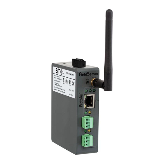
ProtoAir FPA-W44
Start-up Guide
For Interfacing Chromalox Products
To Building Automation Systems:
BACnet MS/TP, BACnet/IP, Modbus TCP/IP, EtherNet/IP, Metasys N2 and
SMC Cloud
APPLICABILITY & EFFECTIVITY
Explains ProtoAir hardware and how to install it.
The instructions are effective for the above as of December 2019.
Document Revision: 9.C
Web Configurator
Template Revision: 4
Advertisement
Table of Contents

Related Manuals for SMC Sierra Monitor Chromalox ProtoAir FPA-W44


Summary of Contents for SMC Sierra Monitor Chromalox ProtoAir FPA-W44
- Page 1 ProtoAir FPA-W44 Start-up Guide For Interfacing Chromalox Products To Building Automation Systems: BACnet MS/TP, BACnet/IP, Modbus TCP/IP, EtherNet/IP, Metasys N2 and SMC Cloud APPLICABILITY & EFFECTIVITY Explains ProtoAir hardware and how to install it. The instructions are effective for the above as of December 2019. Document Revision: 9.C Web Configurator Template Revision: 4...
- Page 2 Chromalox ProtoAir Start-up Guide Technical Support Thank you for purchasing the ProtoAir for Chromalox. Please call Chromalox for technical support of the ProtoAir product. Sierra Monitor Corporation does not provide direct support. If Chromalox needs to escalate the concern, they will contact Sierra Monitor Corporation for assistance. Support Contact Information: Chromalox 1347 Heil Quaker Blvd.
- Page 3 Chromalox ProtoAir Start-up Guide Quick Start Guide 1. Record the information about the unit. (Section 3.1) 2. Check that the ProtoAir and customer device COM settings match. (Section 3.3) 3. Connect the ProtoAir 3 pin RS-485 R1 port to the RS-485 network connected to each of the devices. (Section 4.1) 4.
-
Page 4: Table Of Contents
Chromalox ProtoAir Start-up Guide TABLE OF CONTENTS Certification ............................7 BTL Mark – BACnet ® Testing Laboratory ..................7 Introduction ............................8 ProtoAir Gateway ..........................8 Methods of Configuration ....................... 9 ProtoAir Setup ............................ 10 Record Identification Data ......................10 Point Count Capacity and Registers per Device ................ - Page 5 Chromalox ProtoAir Start-up Guide Appendix B Additional Information ......................49 Appendix B.1 Updating Firmware ......................49 Appendix B.2 BACnet: Setting Network_Number for More Than One ProtoAir on the Subnet ....49 Appendix B.3 Securing ProtoAir with Passwords ..................50 Appendix B.4 Wi-Fi Access Point Network Settings ................51 Appendix B.5 Mounting ...........................
- Page 6 Chromalox ProtoAir Start-up Guide LIST OF FIGURES Figure 1: Method of Configuration per Device ....................9 Figure 2: ProtoAir Part Numbers ......................... 10 Figure 3: Supported Point Count Capacity ....................10 Figure 4: Registers per Device ........................10 Figure 5: COM Settings ..........................11 Figure 6: RS-485 Connections from Devices to the ProtoAir ..............
-
Page 7: Certification
Chromalox ProtoAir Start-up Guide CERTIFICATION BTL Mark – BACnet ® 1 Testing Laboratory The BTL Mark on ProtoAir is a symbol that indicates that a product has passed a series of rigorous tests conducted by an independent laboratory which verifies that the product correctly implements the BACnet features claimed in the listing. -
Page 8: Introduction
Chromalox ProtoAir Start-up Guide INTRODUCTION ProtoAir Gateway The ProtoAir wireless gateway is an external, high performance building automation multi-protocol gateway that is preconfigured to automatically communicate between Chromalox’s devices (hereafter simply called “device”) connected to the ProtoAir and automatically configures them for BACnet/IP, BACnet ®2 MS/TP, Modbus TCP/IP, EtherNet/IP and Metasys It is not necessary to download any configuration files to support the required applications. -
Page 9: Methods Of Configuration
Chromalox ProtoAir Start-up Guide Methods of Configuration Devices Communication ITC1 Modbus RTU & Modbus TCP/IP ITC2 Modbus RTU & Modbus TCP/IP ITLS4 Modbus RTU & Modbus TCP/IP ITLS6 Modbus RTU & Modbus TCP/IP ITLS_2016 Modbus RTU & Modbus TCP/IP Modbus RTU & Modbus TCP/IP CFW_400_600A Modbus RTU &... -
Page 10: Protoair Setup
Chromalox ProtoAir Start-up Guide PROTOAIR SETUP Record Identification Data Each ProtoAir has a unique part number located on the side or the back of the unit. This number should be recorded, as it may be required for technical support. The numbers are as follows: Model Part Number ProtoAir... -
Page 11: Configuring Device Communications
Chromalox ProtoAir Start-up Guide Configuring Device Communications 3.3.1 Confirm the Device and ProtoAir COM Settings Matc h • Any connected serial device MUST have the same baud rate, data bits, stop bits, and parity settings as the ProtoAir. • Figure 5 specifies the device serial port settings required to communicate with the ProtoAir. -
Page 12: Interfacing Protoair To Devices
Chromalox ProtoAir Start-up Guide INTERFACING PROTOAIR TO DEVICES Device Connections to ProtoAir The ProtoAir has a 3-pin Phoenix connector for connecting RS-485 devices on the R1 port. NOTE: Use standard grounding principles for RS-485 GND. ProtoAir Device Pins Pin Label Assignment RS-485 + RS-485 +... -
Page 13: Bias Resistors
Chromalox ProtoAir Start-up Guide Bias Resistors R1 Bias Resistor DIP Switches (2 and 3) R2 Bias Resistor DIP Switches (2 and 3) Figure 8: Bias Resistor DIP Switches To enable Bias Resistors, move both the BIAS- and BIAS+ dip switches to the right as shown in Figure The ProtoAir bias resistors are used to keep the RS-485 bus to a known state, when there is no transmission on the line (bus is idling), to help prevent false bits of data from being detected. -
Page 14: Termination Resistor
Chromalox ProtoAir Start-up Guide Termination Resistor R1 Termination Resistor DIP Switch (1) R2 Termination Resistor DIP Switch (1) Figure 9: Termination Resistor DIP Switch If the ProtoAir is the last device on the serial trunk, then the End-Of-Line Termination Switch needs to be enabled. -
Page 15: Power-Up Protoair
Chromalox ProtoAir Start-up Guide Power-Up ProtoAir Check power requirements in the table below: Power Requirement for ProtoAir External Gateway Current Draw Type ProtoAir Family 12VDC 24VDC/AC FPA – W44 (Typical) 250mA 125mA NOTE: These values are ‘nominal’ and a safety margin should be added to the power supply of the host system. -
Page 16: Connect The Pc To The Protoair
Chromalox ProtoAir Start-up Guide CONNECT THE PC TO THE PROTOAIR Connecting to the ProtoAir via Ethernet Connect a Cat-5 Ethernet cable (straight through or cross-over) between the local PC and ProtoAir. Ethernet Port Figure 12: Ethernet Port Location 5.1.1 Changing the Subnet of the Connected PC The default IP Address for the ProtoAir is 192.168.1.24, Subnet Mask is 255.255.255.0. -
Page 17: Network Settings
Chromalox ProtoAir Start-up Guide NETWORK SETTINGS Navigate to the FS-GUI Network Settings • Navigate to the IP Address of the ProtoAir on the local PC by opening a web browser and entering the IP Address of the ProtoAir; the default Ethernet address is 192.168.1.24. NOTE: If the IP Address of the ProtoAir has been changed, the IP Address can be discovered using the FS Toolbox utility. -
Page 18: Figure 14: Fs-Gui Landing Page
Chromalox ProtoAir Start-up Guide • Find the Navigation tree on the left side of the screen. Figure 14: FS-GUI Landing Page • Click the orange arrow next to the ProtoAir CN number and title to expand the tree. • Click on the orange arrow next to Setup to expand the tree. •... -
Page 19: Change The Protoair Ip Address
Chromalox ProtoAir Start-up Guide Change the ProtoAir IP Address Configure the IP settings of the ProtoAir using the following methods: • When using the Ethernet port to connect to the local network (Section 6.2.1). • When connecting the ProtoAir to a local wireless network, configure the Wi-Fi Client Settings in the ProtoAir (Section 6.2.2). -
Page 20: 6.2.1 Update Wired Network Settings
Chromalox ProtoAir Start-up Guide 6.2.1 Update Wired Network Settings IP Settings tab is the landing page when selecting Network Settings on the navigation tree. To change the IP settings, follow these instructions: • Enable DHCP Client State to automatically assign IP Settings or modify the settings manually as needed, via these fields: IP Address, Netmask, Default Gateway and Domain Name Server1/2. -
Page 21: 6.2.2 Update Wi-Fi Client Settings
Chromalox ProtoAir Start-up Guide 6.2.2 Update Wi-Fi Client Settings From the FS-GUI Network Settings landing page, click on the Wi-Fi Client tab. To change the Wi-Fi client settings, follow these instructions: • Set the Wi-Fi Status to ENABLED for the ProtoAir to communicate with other devices via Wi-Fi. •... -
Page 22: 6.2.3 Common Settings
Chromalox ProtoAir Start-up Guide 6.2.3 Common Settings The Common Settings make it possible to choose the primary connection when both Ethernet and Wi-Fi Client connections are available. • From the FS-GUI Network Settings landing page, click on the Common tab. NOTE: The default is Primary Connection is Ethernet. -
Page 23: Access The Protoair Web App
Chromalox ProtoAir Start-up Guide ACCESS THE PROTOAIR WEB APP Navigate Back to the Web App Landing Screen • Beneath the FS-GUI navigation panel, find and click the Home button. Figure 19: FS-GUI Status Screen The Web App Landing Page will appear Page 23 of 58... -
Page 24: Logging Into The Protoair Web App
Chromalox ProtoAir Start-up Guide Logging into the ProtoAir Web App • Once at the Web App splash page, click the Login button. Figure 20: Web App Login • Enter the previously set up or default username and password. NOTE: The default username is “admin”. The default password is “admin”. Figure 21: Login Window Page 24 of 58... -
Page 25: Figure 22: Generic Web App Page - First Login
Chromalox ProtoAir Start-up Guide When first logging onto the ProtoAir, the Web App will open on the SMC Cloud™ page. Appendix B.7 NOTE: If a warning message appears instead, go to to resolve the connecton issue. Figure 22: Generic Web App Page – First Login •... -
Page 26: Smc Cloud User Setup, Registration And Login
Chromalox ProtoAir Start-up Guide SMC CLOUD USER SETUP, REGISTRATION AND LOGIN The SMC Cloud is Sierra Monitor’s device cloud solution for IIoT. Integration with the SMC Cloud enables a secure remote connection to field devices through a FieldServer and hosts local applications for device configuration, management, as well as maintenance. -
Page 27: Figure 25: Setting User Details
Chromalox ProtoAir Start-up Guide • Click the “Complete Registration” button and fill in user details accordingly. Figure 25: Setting User Details • Fill in the name, phone number, password fields and click the checkbox to agree to the privacy policy and terms of service. •... -
Page 28: Registration Process
Chromalox ProtoAir Start-up Guide Registration Process Once SMC Cloud user credentials have been generated, the ProtoAir can be registered onto the SMC Cloud server. • When first logging onto the ProtoAir, the Web App will open on the SMC Cloud™ page. -
Page 29: Figure 27: Smc Cloud Registration - Installer Details
Chromalox ProtoAir Start-up Guide • To register, fill in the user details, site details, gateway details and SMC Cloud account credentials. Enter user details and click Next Figure 27: SMC Cloud Registration – Installer Details Enter the site details by entering the physical address fields or the latitude and longitude then click Next Figure 28: SMC Cloud Registration –... -
Page 30: Figure 29: Smc Cloud Registration - Gateway Details
Chromalox ProtoAir Start-up Guide Enter Name and Description (required) then click Next Figure 29: SMC Cloud Registration – Gateway Details Enter user credentials and click Register Device Figure 30: SMC Cloud Registration – SMC Cloud Account Page 30 of 58... -
Page 31: Figure 31: Device Registered For Smc Cloud
Chromalox ProtoAir Start-up Guide • Once the device has successfully been registered, a confirmation window will appear. Click the Close button and the following screen will appear listing the device details and additional information auto-populated by the ProtoAir. Figure 31: Device Registered for SMC Cloud NOTE: Update these details at any time by going to the SMC Cloud™... -
Page 32: Login To Smc Cloud
Chromalox ProtoAir Start-up Guide Login to SMC Cloud After the ProtoAir is registered, go to www.smccloud.net and type in the appropriate login information as per registration credentials. Figure 32: SMC Cloud Login Page NOTE: If the login password is lost, see the SMC Cloud Start-up Guide for recovery instructions. -
Page 33: Figure 34: Smc Cloud Landing Page
Chromalox ProtoAir Start-up Guide NOTE: For additional SMC Cloud instructions see the SMC Cloud Start-up Guide. Figure 34: SMC Cloud Landing Page Page 33 of 58... -
Page 34: Configure The Protoair
Chromalox ProtoAir Start-up Guide CONFIGURE THE PROTOAIR Navigate to the ProtoAir W eb Configurator • From the new Web App landing page (Figure 35), click the Settings tab and then click Configuration. Figure 35: New Web App Landing Page Appendix B.8. -
Page 35: Select Field Protocol And Set Configuration Parameters
Chromalox ProtoAir Start-up Guide Select Field Protocol and Set Configuration Parameters • On the Web Configurator page, the first configuration parameter is the Protocol Selector. Figure 37: Web Configurator Showing Protocol Selector Parameter • Select the field protocol by entering the appropriate number into the Protocol Selector Value. Click the Submit button. -
Page 36: Setting The Protoair Active Profiles
Chromalox ProtoAir Start-up Guide Setting the ProtoAir Active Profiles • In the Web Configurator, the Active Profiles are shown below the configuration parameters. The Active Profiles section lists the currently active device profiles, including previous Web Configurator additions. This list is empty for new installations, or after clearing all configurations. (Figure Figure 38: Web Configurator Showing no Active Profiles Page 36 of 58... -
Page 37: Verify Device Communications
Chromalox ProtoAir Start-up Guide • To add an active profile to support a device, click the Add button under the Active Profiles heading. This will present a drop-down menu underneath the Current profile column that lists all the available profiles. •... -
Page 38: Bacnet: Setting Node_Offset To Assign Specific Device Instances
Chromalox ProtoAir Start-up Guide BACnet: Setting Node_Offset to Assign Specific Device Instances • Follow the steps outlined in Section to access the ProtoAir Web Configurator. • The Node_Offset field shows the current value (default = 50,000). The values allowed for a BACnet Device Instance can range from 1 to 4,194,303 •... -
Page 39: How To Start The Installation Over: Clearing Profiles
Chromalox ProtoAir Start-up Guide How to Start the Installation Over: Clearing Profiles • Follow the steps outlined in Section to access the ProtoAir Web Configurator. • At the bottom-left of the page, click the “Clear Profiles and Restart” button. • Once restart is complete, all past profiles discovered and/or added via Web configurator are deleted. -
Page 40: Appendix A Troubleshooting
Chromalox ProtoAir Start-up Guide Appendix A Troubleshooting Appendix A.1 Lost or Incorrect IP Address • Ensure that FieldServer Toolbox is loaded onto the local PC. Otherwise, download the FieldServer-Toolbox.zip via the Sierra Monitor website’s Software Downloads. • Extract the executable file and complete the installation. Ethernet Port Figure 43: Ethernet Port Location •... -
Page 41: Appendix A.2 Viewing Diagnostic Information
Chromalox ProtoAir Start-up Guide Appendix A.2 Viewing Diagnostic Information • Type the IP Address of the ProtoAir into the web browser or use the FieldServer Toolbox to connect to the ProtoAir. • Click on Diagnostics Button, then click on view, and then on connections. •... -
Page 42: Appendix A.3 Checking Wiring And Settings
Chromalox ProtoAir Start-up Guide Appendix A.3 Checking Wiring and Settings • No COMS on Modbus RTU side. If the Tx/Rx LEDs are not flashing rapidly then there is a COM issue. To fix this, check the following: A.4) Visual observations of LEDs on ProtoAir (Appendix Check baud rate, parity, data bits, stop bits Check Detector ID matches the correct device... -
Page 43: Appendix A.4 Led Diagnostics For Communications Between Protoair And Devices
Chromalox ProtoAir Start-up Guide Appendix A.4 LED Diagnostics for Communications Between ProtoAir and Devices See the diagram below for ProtoAir FPA-W44 LED Locations. FPA-W44 Diagnostic LEDs Description The SS LED will flash once a second to indicate that the bridge is in operation. The SYS ERR LED will go on solid indicating there is a system error. -
Page 44: Appendix A.5 Taking A Fieldserver Diagnostic Capture
Chromalox ProtoAir Start-up Guide Appendix A.5 Taking a FieldServer Diagnostic Capture When there is a problem on-site that cannot easily be resolved, perform a diagnostic capture before contacting support so that support can quickly solve the problem. There are two methods for taking diagnostic captures: •... - Page 45 Chromalox ProtoAir Start-up Guide • Step 1: Take a Log Click on the diagnose icon of the desired device Ensure “Full Diagnostic” is selected (this is the default) NOTE: If desired, the default capture period can be changed. Page 45 of 58...
- Page 46 Chromalox ProtoAir Start-up Guide Click on “Start Diagnostic” Wait for Capture period to finish, then the Diagnostic Test Complete window will appear • Step 2: Send Log Once the Diagnostic test is complete, a .zip file is saved on the PC Choose “Open”...
-
Page 47: Appendix A.5.2 Using Fs-Gui
Chromalox ProtoAir Start-up Guide Appendix A.5.2 Using FS-GUI Diagnostic Capture via FS-GUI is only available on FieldServers with a bios updated/released on November 2017 or later. Completing a Diagnostic Capture through the FieldServer allows network connections (such as Ethernet and Wi-Fi) to be captured. Once the Diagnostic Capture is complete, email it to technical support. -
Page 48: Appendix A.6 Wi-Fi Signal Strength
Chromalox ProtoAir Start-up Guide Appendix A.6 Wi-Fi Signal Strength Wi-Fi <60dBm – Excellent <70dBm – Very good <80dBm – Good >80dBm – Weak Figure 47: Wi-Fi Signal Strength Listing NOTE: If the signal is weak or spotty, try to improve the signal strength by checking the antenna and the ProtoAir position. -
Page 49: Appendix B Additional Information
Chromalox ProtoAir Start-up Guide Appendix B Additional Information Appendix B.1 Updating Firmware To load a new version of the firmware, follow these instructions: 1. Extract and save the new file onto the local PC. 2. Open a web browser and type the IP Address of the FieldServer in the address bar. Default IP Address is 192.168.1.24 A.1) Use the FS Toolbox utility if the IP Address is unknown... -
Page 50: Appendix B.3 Securing Protoair With Passwords
Chromalox ProtoAir Start-up Guide Appendix B.3 Securing ProtoAir with Passwords Access to the ProtoAir can be restricted by enabling a password on the FS-GUI Passwords page – click Setup and then Passwords in the navigation panel. There are 2 access levels defined by 2 account names: Admin and User. -
Page 51: Appendix B.4 Wi-Fi Access Point Network Settings
Chromalox ProtoAir Start-up Guide Appendix B.4 Wi-Fi Access Point Network Settings From the FS-GUI Network Settings landing page, click on the Wi-Fi AP tab. To change the Wi-Fi AP settings, follow these instructions: • The Access Point Status Field must be ENABLED to allow connecting to the ProtoAir via Wi-Fi. •... -
Page 52: Appendix B.5 Mounting
Chromalox ProtoAir Start-up Guide Appendix B.5 Mounting The ProtoAir can be mounted using the DIN rail mounting bracket on the back of the unit. Din Rail Bracket Figure 52: DIN Rail Page 52 of 58... -
Page 53: Appendix B.6 Physical Dimension Drawing
Chromalox ProtoAir Start-up Guide Appendix B.6 Physical Dimension Drawing Power Port Wi-Fi Antenna Socket R2 Serial Port R1 Serial Port Figure 53: ProtoAir FPA-W44 Dimensions Page 53 of 58... -
Page 54: Appendix B.7 Smc Cloud Connection Warning Message
Chromalox ProtoAir Start-up Guide Appendix B.7 SMC Cloud Connection Warning Message • Figure 26, follow the suggestion If a warning message appears instead of the page as shown in that appears on screen. If the ProtoAir cannot reach the SMC Cloud server, the following message will appear Figure 54: SMC Cloud Connection Problems Message •... -
Page 55: Appendix B.8 System Status Button
Chromalox ProtoAir Start-up Guide Appendix B.8 System Status Button The System Status Button can be found on any page of the web apps. This shows the level of alert/functionality for the customer device. This is an agragate of the Web App page’s resource usage upon the local PC or mobile device, SMC Cloud connectivity and device alert level. -
Page 56: Appendix C Vendor Information - Chromalox
Chromalox ProtoAir Start-up Guide Appendix C Vendor Information – Chromalox See the document “Chromalox Vendor Mappings” for the complete point list for all the Chromalox devices referenced in this manual. Only the protocols listed as supported for this FieldServer are supported (see Section 2.1). -
Page 57: Appendix D Reference
Chromalox ProtoAir Start-up Guide Appendix D Reference Appendix D.1 Specifications ProtoAir FPA-W44 One 3-pin Phoenix connector with: RS-485/RS-232 port (TX+/RX-/gnd) One 3-pin Phoenix connector with: RS-485 (Tx+/Rx-/gnd) Electrical Connections One 3-pin Phoenix connector with: Power port (+/-/Frame-gnd) One Ethernet 10/100 BaseT port Input Voltage: 9-30VDC or 24VAC Current draw: 24VAC 0.125A Power Requirements... -
Page 58: Appendix E Limited 2 Year Warranty
Chromalox ProtoAir Start-up Guide Appendix E Limited 2 Year Warranty Sierra Monitor Corporation warrants its products to be free from defects in workmanship or material under normal use and service for two years after date of shipment. Sierra Monitor Corporation will repair or replace any equipment found to be defective during the warranty period. Final determination of the nature and responsibility for defective or damaged equipment will be made by Sierra Monitor Corporation personnel.
Need help?
Do you have a question about the Chromalox ProtoAir FPA-W44 and is the answer not in the manual?
Questions and answers