Table of Contents
Advertisement
Quick Links
CAUTION: It is recommended that the user of
this equipment become acquainted with the infor
mation in these instructions before energizing the
relay. Failure to do so may result in damage to the
equipment. Before putting the relay into service,
operate the relay to check the electrical connec
tions.
Printed circuit modules should not be removed or
inserted while the relay is energized. Failure to
observe this precaution may result in an undesired
tripping output or cause component damage.
APPLICATION
The SBF -1 is a solid state breaker failure
detection relay with contact output. It is used in
conjunction with the primary and backup relays.
Other logic inputs (such as the 52a contact) may
be used where the fault current is insufficient to
operate the current detector.
The relay is applicable with any of the
bus/breaker schemes in general use.
Provision is included in the relay for "retrip
ping" the breaker without time delay. This may
avoid clearing a bus during incorrect maintenance
procedure or due to the failure of a trip contact to
close.
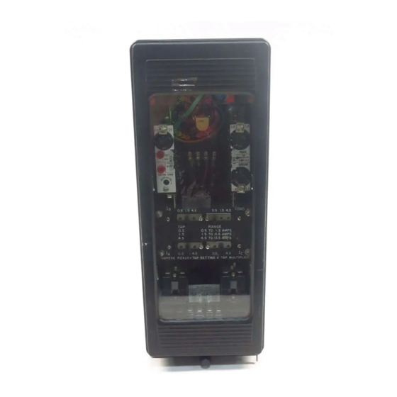
C O N STRUCTION
The SBF-1 Relay consists of a phase and
ground current detector, a breaker failure timer, a
control timer, a seal-in
relay (AR) along with 2 indicating contactor
switches (ICS).
I// {)()lsih/e conringencies 11·hich mar arise during installation. operation. or maintenance. and all
derai/1 and 1ariarinm of rhis equipmenr do not purport to be covered h1· these instructions. !/further
in/nml!lrinn is desired h1· r)[lrcha.1er regarding his particular instal/arion. operation or maintenance of
"'
cc{lli{JIIICIIr. rhe fond We.lfinghouse E/ecrric Corporation representati1·e should he contacted.
'
N EW I NFORMATION
INSTALLATION
INSTRUCTli®NS
TYPE SBF-1 CIRCUIT BREAKER
FAILURE RELAY
(X)
relay and an output
Westinghouse I.L. 41-776.5
•
OPERATION
Overcurrent Detector
T h e detector consists o f 3 or 4 input
transformers and a plug in m odule. The primary o f
the transformer i s tapped and brought out to a tap
block located on the front of the relay. Each
transformer has three taps which cover the range
of pickup.
The secondary of the transformers are con
nected to the input of the plug-in detector m odule
where the phase and ground signals are connected
to separate pickup level adjustments located on the
front of the module. A comparator circuit consists
of a plug-in operational amplifer whose output is
connected to logic circuitry which controls the A R
output relay.
Also located on the module is a reed relay
( RR) which is controlled by the breaker failure
(BF) timer on the timer module. The normally
open contacts of the reed relay are connected in the
current detector circuit and controls the operation
of the circuit.
B F and Control Timer
These timers are located on the timer plug-in
module.
The BF timer can be continuously varied over
the range by means of an adjusting knob located at
the front of the module. A calibrated scale permits
setting the desired time delay. A test jack is also
located at the front if it is desired to check the set
ting with an electronic test timer.
At the bottom of the front plate is an access
hole which permits adjusting the control timer
EFFECTIVE N OVEMBER 1978
•
MAINTENANCE
Advertisement
Table of Contents

Related Manuals for Westinghouse SBF-1


Summary of Contents for Westinghouse SBF-1
- Page 1 C O N STRUCTION setting the desired time delay. A test jack is also The SBF-1 Relay consists of a phase and located at the front if it is desired to check the set ground current detector, a breaker failure timer, a ting with an electronic test timer.
- Page 2 to the level detector. This arrangement keeps the trim pot. A test jack is also supplied to change the control timer delay in conjunction with a tester if overcurrent input transformer load at a low level. other than the factory setting is desired. This permits fast reset of the secondary voltage of 3 ms or less, even at very high multiples of pickup current.
- Page 3 I.L. 41-776.5 (Q6). The other input controlling transistor Q5 is Control Timer either the 52a contact input (if used) connected to The range of the control timer is 1 50 to 250 ms. relay terminal 1 8 or operation of the overcurrent The timer as received should be set for ap...
- Page 4 Relay Rating BF Timer Setting Capacitance safely carry this current long enough to trip a cir cuit breaker. 48 Vdc 1 8 MFD or higher SETT I N G S 1 25 Vdc 6 MFD or higher 1 25 Vdc 1 3 MFD or higher OVE R C U R RENT D ETECTOR...
-
Page 5: Installation
I.L. 41-776.5 t a p a n d u s e a t y p e WL r e l a y w i t h a relay pickup (3 to 5 ms) and operate time of the S#304C209G0 1 coil or equivalent. ojc unit (3 to 8 ms). - Page 6 module and apply rated de voltage. Also apply module to a multiturn potentiometer. Use the elec phase current to phase A input. The voltage at test tronic test timer in the manner described to obtain point TP3 on the overcurrent module should drop the desired time interval.
- Page 7 I.L. 41-776.5 To mark the dial, first jumper test point TP6 Indicating Contactor and TP7 on the timer board. Energize the relay Switch ( I C S) with rated de voltage and apply 0.48 Amps ac There are two I CS units used. Each may be current to phase A.
-
Page 8: Troubleshooting
slippage of the knob pointer on the shaft, this can a . Apply rated relay voltage. Voltage at lower be corrected by rotating the shaft fully CCW. N ow test jack = 23 . 5 V adjust the knob at the pin prick mark. This should b . -
Page 9: Renewal Parts
I.L. 41-776.5 8 . Ju mper test point TP6 and TP7. Apply twice terminal 3 should measure 2 3 . 5 Vdc before tap value ac current. the output relay operates and less than 2 . 5 V after i t operates . a . - Page 10 TABLE I E N E R GY R E Q U I REM E NTS 60 H Z 3 ( 1 .5A P I C K U P) TAP M U LT. 1 (0.5A PIC K U P) R E E D ( R R) CO NTACT O P E N* CL OS ED...
- Page 11 I.L. 41-776.5 TABLE 3 C U R R E N T RAT I N G C U R R E NT R A N G E ( Phase a n d Ground) 0.5 to 1 3.5 Amperes TAP R A N G ES C O N TI N U O U S 1 S E C O N D 0 .
- Page 12 SEAL-IN RELAY (X) TRANSFORMER TB TRANSFORMER TA ICS INDICATING CONTACTOR SWITCH Fig. 1. Photograph of SBF-1 Relay, (without case) with four overcurrent input. Front view...
- Page 13 I.L. 41-776.5 POTENTIOMETER PA POTENTIOMETER PC POTENTIOMETER PG TRANSFORMER TG RESISTOR RS (right oblique).
- Page 14 LEFT CENTER S RIGHT CENTER POSITI ONS. RESISTORS REF. DWG. V OLTS DC 1326DI9- DETAILED SCHEMATIC 900Il. 200Il. 1326D31- ( 4 OVERCURRENT UNITS) WIRING 315011 IOOO.!l 1326D83- ( 3 OVERCURRENT UNITS W IRING 7100.!1 2500Il. Dwg. 7758813 Fig. 2. Simplified Internal Schematic SBF-1 Relay.
- Page 15 I.L. 41-776.5 POS. 14� 24VDC TO X RELAY POS. 24VDC RATED VDC 13 FROM TERM. 3 OF OVERCURRENT DETECTOR MODULE RATED VDC TIMER AND O UTPUT MODULE PI IS PANEL MOUNTED WHEN USED REPLACED FOR GROUPS Fig. 4. Internal SCR...
- Page 16 1454C81 GOI 1454C81 G02 1454C81G03 (48 voc) (125 VOC) (250 VOC) I TOR CAPt;CJ I� DESCfUPTI0\1 CAPAC Dt:SCRI PTI ON STYLE CAPAC! HIR OESCH I PTI 0:'-l STYLE N0, .::!70UF 180A66':1H05 • 270UF 200V !88A669H05 A669H0 5 .270UF 20PV .o.soour J , 300UF 3"...
- Page 17 I.L. 41-776.5 Pl-2 Pl-3 3517A76 Fig. 5. Component Location tor Timer Module 48 or 125Vdc rated relay...
- Page 18 WHEN USED 3517A77 Fig. 6. Com ponent Location for Timer Mod I u e 250Vdc rated relay.
- Page 19 POS . TO TERM . 4 OF TIMER OUTPUT MODULE I41NPUTI ( 31NPUTI 1454C79G01 J454C79G02 Ci[cJ,t ::.uu: L!r_:_,:.;"I''TI.,,.,J CAPAC! TJI( DO::: S CrUI'Tl�,-._ Sf'I'LE {1 0 , 27u1JF ?ul:v loc;\b6'fH0":> lii6A669HO� " .2-IOUF 200V WHEN USED) •l!OtJfo: Dr::oCRI t'TI �.'J S TYLt::: '<.!.
- Page 20 3517A78 Fig. 8. Component Location for 3 Current Input Overcurrent Detector Module.
- Page 21 I.L. 41-776.5 3517A79 Fig. 9. Component Location for 4 Current Input Overcurrent Detector Module.
- Page 22 D START TO TEST TIMER (COMMON) NOTE: TO TEST FOR OVER CURRENT UNIT PICKUP, JUMPER TIMER BOARD TEST POINT TP6 AND TP7 BEFORE ENERGIZING RELAY. TEST BKR FL TIMER IN SIMILAR MANNER. 1479829 Fig. 10. Test Diagram for SBF-1 Relay.
- Page 23 ':" RELAYS SPP SURGE PROTECTION TRANSMISSION LINE OR TRANSFORMER CAPACITOR S TO BE USED WHEN SURGE VOLTAGE MAY EXCEED 2500 VOLTS PEAK LEGEND DESCRIPTION CIRCUIT BREAKER SBF-1 BREAKER FAILURE RELAY(7 7 58813, 1326019) ..-1>. ""' -1>. .:..,...
- Page 24 ISOLATES A TR ANSFOR MER LEGEND DESCR IPTION e6TI CIR CUIT BR EAKER tSPP SBF-1 BR EAKER FAILUR E R ELAY ( 7nBBI3,1326DI 9 ) 62- 1 62Xp2 Y BR EAKER FAIL U R E INITIATE CONTACTS 8 6 BF BR EAKER...
- Page 25 . 1 90 - 32 SCREW 4 . 3 7 5 SPACERS FOR ( I l l . 1 3 ) THIN PAN E L S 5707903 Fig. 13. Outline and Drilling Plan for SBF-1 relay in the Type FT-32 Case. Dwg.
- Page 28 W E S T I N G H O U S E E L E C T R I C C O R P O R A T I O N R E LAY - I NST R U M E NT D IV IS I O N C O R A L S P R I N GS, F L.
-
Page 29: Fail Ure Relay
O P E R A T I O N M A I N T E N A N C E TY P E SBF-1 C I RC U I T BREAKER FAIL URE RELAY CAUTION: I t is recommended that the user of Overcurrent Detector this equipment become acquainted with the infor... -
Page 30: Power Supply
trim pot. A test jack is also supplied to change the OPERAT IO N control timer delay in conj unction with a tester if other than the factory setting is desired. The operation of the SBF- 1 i s somewhat different than the conventional breaker failure A level detector circuit consisting of zener relay. - Page 31 I. L. 41-776.5A time out first since it is always set for a shorter CAUTION: Since the tap block connector screw delay. The output of the BF timer is connected to carries operating current, be sure that the screw terminal 9 of the timer m odule which is wired to is turned tight.
- Page 32 I t can be energized continuously at 1 1 0% of on the 0.2 amp tap and 0. 1 5 ohms on the 2.0 amp rated input voltage. tap. TRIP C I R C U IT C apacitive Effect The capacitive surge immunity is as follows The main contacts will safely close 30 amperes (considering the 52a contact input present): at 250 Vdc and the seal-in contacts of the I CS will...
- Page 33 1 6 must be included. A secure m argin for the SBF-1 milli seconds longer than the B F timer. This allows cycles . (33 ms)
-
Page 34: Acceptance Test
Acceptance Test timer to the relay so that the start input is con- nected to relay terminal 9 (through a voltage The following check is recom mended to insure divider, if necesary). The stop input should be con- that the relay is i n proper working order. Refer to nected to the bottom test jack on the timer Fig. - Page 35 I. L. 41-776.5A Remove jumper from test point TP6 and TP7 Calibration on the timer module. Use the following procedure for calibrating the relay if the relay has been taken apart for repairs Now when the test switch to terminal 9 is clos or the adj ustments have been disturbed.
- Page 37 I. L. 41-776.5A a . With 0.4 amp ac current flowing apply rated mately 0. 1 V less than voltage measured in relay voltage. M easure voltage at terminal 5 section a. of I C I to be 6.4V. N ow increase the current 6.
- Page 38 TABLE I E N E R GY R E Q U I R E M ENTS 60 HZ TAP M U LT. 1 (0.5A P I C K U P) 3 ( 1 .5A P I C K U P ) R E E D ( R R) C O NTACT O PE N*...
- Page 39 I . L. 41-776.5A TABLE 3 C U R R E N T R AT I N G C U R RENT R A N G E ( Phase a n d Ground) 0.5 to 1 3.5 Amperes TAP R A N G E S CONTI N U O U S 1 S E C O N D 0 .
- Page 40 SEAL-IN RELAY (X) TRAN SFORMER TB TRANSFORMER TA ICS INDICATING CONTACTOR SWITCH Fig. 1. Photograph of SBF-1 Relay, (without case) with four overcurrent input. Front view...
- Page 41 I. L. 41-776.5A P OTENTIOMETER P A POTENT! OMETER PC POTENTI OMETER PG TRANSFORMER TG RESISTOR RS (right oblique).
- Page 43 I. L. 41-776.5A POS. 14 � 24 VDC TO X R E L AY POS. 24 VDC RATED VDC FROM T E R M . 3 OF OVERCURRENT DETECTOR MODULE RATED VDC T I M E R AND O U T P U T M O D U L E PI IS PA N E L MOUNTED WHEN USED B Y J...
- Page 45 I. L. 41-776.5A "-- Pl-2 Pl-3 351 7A 76 Fig. 5. Component Location for Timer Module or 1 25 Vdc rated relay...
- Page 46 WHEN USED 351 7A 77 Fig. Comp anent Location for Timer Mod e 250Vdc rated relay.
- Page 47 P O S , 24 VDC TO TE R M . 4 OF TIMER OUTPUT 1454C79GOI 1454C79G02 MODULE (3 INPUT! I N P U T ) 1:M'ACI r u r< -'IIOJ� u . _ s c r< I P T I J,\l S T Y I .
- Page 48 351 7A 78 8. Component Location for 3 Current Input Overcurrent Detector Module. Fig.
- Page 50 TO TEST Tl MER (COMMON) NOTE: TO TEST FOR OVERCURRENT UN I T PICKUP, JUMPER TIMER BOARD TEST POINT TP6 AND TP7 BEFORE ENERGIZING RELAY. TEST BKR FL TIMER IN SIMILAR MANNER. 1479829 Fig. 10. Test Diagram for SBF-1 Relay.
- Page 51 S P P SURGE PROTECTION TRANSMISSION LINE OR TRAN SFORMER CAPACITORS TO BE USED WHEN SURGE VOLTAGE MAY EXCEED 2500 VOLTS PEAK LEGEND DESCRIPTION SBF-1 BREAKER FAILURE RELAY( 7 7 58813, 1326019) .,.."" 0> "" .:..
- Page 52 -- ----· ] R E Q U I R E D WHERE PROTECTED � BREA K E R ISOLATES A TRANSFORMER � L E G E N D DC P O S � , , ________ _____ � :: _( 1 - - - -�---- a6T ' C I R C U I T...
- Page 53 I. L. 41-776.5A HOLES FOR D I A . SCREWS MTG. 15.750 ( 4 00.05) 5. 875 1 4 9 16. 500 (419. 1 ) ( 8 0. 9 8) (74.63 ) PA N E L C U TO U T DR I L L I N G 6.375 1 6 1...
- Page 56 W E S T I N G H O U S E E L E C T R I C C O R P O R A T I O N R E LAY - I N ST R U M E NT D I V I S I O N C O R A L S P R I N G S, F L.
Need help?
Do you have a question about the SBF-1 and is the answer not in the manual?
Questions and answers