Advertisement
Quick Links
TYPE IRV DIRECTIONAL OVERCURRENT RELAY
C A U T I O N Before putting relays into service, remove
all blocking which may have been inserted for the
purpose of securing the parts during shipment, make
sure that all moving parts operate freely, inspect the
contacts to see that they are clean and close properly,
and operate the relay to check the settings and
electrical connections.
A P P L I CA T I ON
These relays are phase directional overcurrent
relays which are used for the protection of trans
mission lines and feeder circuits. Both the time
overcurrent and instantaneous overcurrent units are
directionally controlled.
C O N S T RUCTION AN D O P E RATION
The Type IRV relay consists of a directional
unit (D), an auxiliary switch (Cs-1), a time-overcurrent
unit (CO), an instantaneous overcurrent unit
instantaneous overcurrent unit transformer, and two
indicating contactor switches (ICS/I) and (ICS/T).
The principle component parts of the relays and their
location are shown in Fig. 1 and 2.
T i m e- O v er c u rrent U n i t ( C O )
The electromagnets for the types C0-5, C0-6,
C0-7, CQ-8 and C0-9 units have a main tapped coil
located on the center leg of an "E" type laminated
structure that produces a flux which divides and re
turns through the outer legs. A shading coil causes
the flux through the left leg to lag the main pole flux.
The out-of-phase fluxes thus produced in the air ga p
causes a contact closing torque.
The electromagnet for the type C0 - 2 and C0-11 units
have a main coil consisting of a tapped primary wind
ing and a secondary winding. Two identical coils on
the outer legs of the lamination structure are connect
ed to the main coil secondary in a manner so that the
combination of all the fluxes produced by the electro
magnet result in out-of-phase fluxes in the air gap.
The out-of-phase air gap fluxes produced cause a
contact closing torque.
SUPERSEDES I.L. 41-133.3D
'Denotes change from superseded 1ssue.
I N STA L L A Tl O N
INSTRUCTIONS
FOR PHASE PROTECTION
(I), an
Westinghouse
O P ERAT I O N
•
I n d i c at i ng C o ntactor S w i t c h U n i t s ( I C S/ 1 and I C S/T)
The d-e indicating contactor switch is a small
clapper type device. A magnetic armature, to which
leaf-spring mounted contacts are attached, is attracted
to
the magnetic core upon energization of the switch.
When the switch closes the moving contacts bridge
two stationary contacts, completing the trip circuit.
Also during this operation two fingers on the armature
deflect a spring located on the front of the switch,
which allows the operation indicator target to drop.
The front spring, in addition to holding the target,
provides restraint for the armature and thus controls
the pick-up value of the switch.
D i recti o n al U n i t { D )
The directional unit is a product induction cylin
der type unit operating on the interaction between the
polarizing circuit flux and the operating circuit flux.
Mechanically, the directional unit is composed of
four basic components:
an electromagnet, a moving element assembly, and
molded bridge.
The frame serves as the mounting structure for
the magnetic core. The magnetic core which houses
the lower pin bearing is secured to the frame by a
spring and snap ring. This is an adjustable core
which has a .025 inch flat on one side and is held in
its adjusted position by the clamping action of two
compressed springs. The bearing can be replaced, if
necessary, without having to remove the magnetic
core from the frame.
The
electromagnet
polarizing coils mounted diametrically opposite one
another, two series-connected operating coils mounted
diametrically opposite one another; two magnetic ad
justing plugs; upper and lower adjusting plug clips,
and two locating pins. The locating pins are used to
accurately position the lower pin bearing, which is
mounted on the frame, with respect to the upper pin
bearing, which is threaded into the bridge. The elec-
1. L. 41-l33.3E
MAI N TE N A N C E
•
A die-cast aluminum frame,
has
two series-connected
EFFECTIVE MAY 1971
a
Advertisement

Subscribe to Our Youtube Channel
Related Manuals for Westinghouse IRV


Summary of Contents for Westinghouse IRV
- Page 1 C O N S T RUCTION AN D O P E RATION The directional unit is a product induction cylin The Type IRV relay consists of a directional der type unit operating on the interaction between the unit (D), an auxiliary switch (Cs-1), a time-overcurrent polarizing circuit flux and the operating circuit flux.
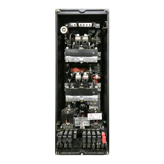
- Page 2 ..-< 1- Unit Tap Block < ,... -< 1. 23 MFD Tripping Rectifier 0. 0 3 MFD Capacitor D Unit CSl Unit Unit ICS - I CO Unit ICS-T Fig. Type I R V R e lay Without Case (Front View). Fig.
-
Page 3: Inverse Time
(e.g., IRV-8). T. burden. The primary winding is tapped and these taps are brought out to a tap block for ease in chang... - Page 4 POLARITY AS SHOWN, THE DIRECTIOIIAL UIIIT COIIT.I.CTS ClOSE been shop adjusted for optimum follow and this ad justment should not be disturbed. Fig. 3. Internal Schematic of the Type IRV Relay in the Trip Circuit Constants Type FT31 Case. Indicating Contactor Switch - 0.2 ampere tap- 6 .
- Page 5 REQUIREMENTS ENERGY - 60 I N ST AN T AN E O U S OV E R CU R R E N T U N I T O P E R A T I N G CU R R E N T CI R CU I T CYCL E S ¢...
-
Page 6: Energy Requirements
ENERGY REQUIREMENTS TYP E I RV-2 TIM E OV E RCURREN T U N I TS VOLT AMPERES t t CONTINUOUS ONE SECOND POWER TIMES TIMES TIMES AMPERE RATING RATING t FACTOR TAP VALUE TAP VALUE TAP VALUE TAP VALUE RANGE (AMPERES) (AMPERES) - Page 7 ENERGY REQUIREMENTS IRV-7 TIME OVERCU RRE NT U NITS VOLT AMPERES t t ONE SECOND TIMES TIMES TIMES POWER AT 10 CONTINUOUS AT 3 RATING RATING FACTOR TAP VALUE TAP VALUE TAP VALUE TAP VALUE (AMPERES) RANGE ANGLE CURRENT CURRENT...
- Page 8 TYPE IRV RELAY ENERGY REQUIREMENTS I RV- 1 1 OVE RCU R R EN T U N I TS VOLT AMPERE s CONTINUC'US ONE SECOND POWER TIMES TIMES TIMES AMPERE RATING RATING FACTOR TAP VALUE TAP VALUE TAP VALUE TAP VALUE...
- Page 9 TY P E I R V R E LAY TYP I CAL T I ME CU RVES TYPE C0-2 O V E R CU RREN T R E L AY 50-60 CYCL ES •. �50 � <D ..J > DIAL SETTING >...
- Page 10 1110 T Y P I CAL T I M E C U R V E S T Y P E C0 - 5 O V E R CU R REN T REL AY 50- 60 C Y CLES ,I I I ll LA.I T I ME...
- Page 12 TYP I CAL T I ME C U �VES T Y P E C0-7 ' ' I OVER CU R R E N T R E L AY � 0 -60 CYC L ES ' ' I <I) T I M E D I A L S ETT I N G <I) 16 JB 20 9 10...
- Page 13 TYP I CAL T I M E CU R V ES TYP E C0-8 O V E R C U R R E N T R E L AY e0-6 0 CYCL ES T I M E D I AL SETT I N G L&.l g 10 16 18 ro...
- Page 14 TYP I CAL T I ME C U R V ES TYPE C0-9 O V E R CU R RENT R E L AY 5 0 - 60 CYCL ES T I M E D I AL S ETT I NG cn 3 16 18 20 9 10...
- Page 15 li 7 8 9 10 288 8655 T Y P I CAL T I NE C U R V E S T Y P E C0- 1 1 � OVER C U R R ENT R E L AY 50-00 CYCL[S �...
- Page 16 TY P E I RV R ELAY T Y P I C A L T I M E C U R V E S C Y L I N D E R I N ST A N TA N EO U S OVE R C U R RENT U N I T ...J ...J...
- Page 17 TY P E I R V RE LAY 1 0 0 T Y P I C A L T I M E C U R V E S D I R EC T I O N A L U N I T F O R C U R R E NT A P P L I E D I N P H A S E...
- Page 18 Contact Gap - The gap between the station ary and moving contacts with th e relay in the de For typ e IRV- 1 1 rei ay only, the L 30 times tap . 0 20 " . energized po sition shoul d be approximately...
- Page 19 I . L . TY P E I R V R ELAY 4 1 - 1 33 . 3 E tim e s pi ck- up current at an exp ected op erating point fo r t h e p arti cul ar ap p l i cation. For t he 2.
- Page 20 respectively. tacts of the unit . Insert the tap s crew i n t h e m ini m um value tap s etting and adjust the sprin g such The magnetic plugs and core are u s e d to that t h e contacts wil l close as i nd icated by a neon reverse any unwanted spurious torques that may b e l am p i n the c o ntact circu i t wh e n en ergized with the...
- Page 21 Apply t h e i n d i c atecl current p er Tab! e 1 for the nent magnet adju stment ( e . g. IRV-8 , 2 tim e s tap val u e ) el ectromagnet p l ug adjustment ( e . g. I R V-8 .
- Page 22 out until the proper operati ng time has been obtained. core when the switch i s picked up. This can b e done by turning the relay upside-down. Then screw up the Recheck th e permanent magnet ad ustment. If th e core screw until the moving core starts rotating.
- Page 23 T A B L E C Y C L E S T I M E C U R V E C AL I B R A T I O N D A T A - ELECTROMAGNET PLUGS PERMANENT MAGNET ADJUSTMENT CURRENT OPERATING TIME...
- Page 24 ( FROII T V I EW) 5'7- D - '7 902 Outline and Drilling Plan fo r the Type IRV Relay in the Type FT3 l Case. Fig. 1 6. W E S T I N G H O U S E...
- Page 25 Westi nghouse t . L . 4 1 -l 33 .2C O PE R A T I O N M A I N T E N A N C E I N S T A L L A TI O N •...
- Page 26 -< "'tt � -< Fig. 2. Type I R Q R elay without Case (Fro n t View) Fig. Type I R Q R e lay without Case ( R ear View)
- Page 27 T Y P E I RQ R E LAY Time Overcurrent Unit (Front View) . 1 - Tap B lo ck, 2 - Time Di al, 3 - Control Spring A s sembly, D i s c, Stationary F ig. 3. Contacts A s sembly, - Magneti c P lugs, ·...
- Page 28 T Y P E I RQ R E L AY "' CURRENT APPLIED AT "' MAXIMUM TORQUE A N G L E ..J "' CONTACTS CLOSE FOR AUTO TRANSFORMER VOLTAGES CURRENTS ::> "' ABOVE TO RIGHT D I R£CTIONAL UNH - -.. THE CURVE .
- Page 29 TYP E I RQ R E LAY . 2 4 CONTACT GAP APPROXIMATELY .020 I N C H . 2 2 REST O F C I RCUIT MillE� -( SAME AS THAT AT LEFT CLOSE CS-1 COIITACT$ . 2 0 TO TEST OYEICUIREIT UIIIT (CO) .
- Page 30 T Y P E I RQ R E L AY ( FRONT VIEW) ADJUST MIDDLE RESISTOR ZERO VOLTAGE v2 , J .n v1 FILTER RESISTOR SLIDER DISCONNECT L E A D RIGHT HAND TERM. LOWER ( RIGOO T SIDr VIE W ) OF MUTUAL REACTOR 0·1�...
- Page 31 T YP E I R Q R E LAY E S O N T H E SEQUENCE VOLTAGE h t. L A Y S T E P P L A C E S T H E f O L L O W I N G P H A S E A N E G a.
- Page 32 T Y P E I R Q R E LAY • TEST NO. POLAR ITY CHECK FOR 1 5 / 5 AMI"ER£ AUXILIARY ------- CURRENT TRANSFORMER OPEN RELAY SWITCH 10 AND FT-1 SWITCH J OPEN RELAY SWI TCH 16 AND JUMPER SWITCH JAWS �.
- Page 33 T Y P E I RQ R E LAY PHASE ROTATION STATION !US 1 , 2 , 5 liST li"" IT SEC. 6 7N -.--- 6 7 N D E V I C E N U M B E R CHART D I R E C T I O N A L OVERCURRENT...
- Page 34 T Y P E I R Q R ELAY "0" mark approximately . 0 20 " . The placement o f the various time dial po �itions i n line with the index mark will give operating times as shown on the re •t-' �...
- Page 35 TY P E I RQ R EL A Y T Y P I CAL T I M E C U R V E S C Y L I N D E R I N STA NTANEOUS OVERCU RRENT U N I T M U LT I P L E S O F TAP VA L U E C U R R E N T 184A946 F i g.
- Page 36 TY PE I R Q R E LAY N e g a t i v e S e q u e n c e C u r r e n t F i l t e r notches located on the periphery o f the spring ad j uster and rotating it.
- Page 37 •2 c T Y P E I RQ R E L AY 3) Time Curve Calibration - In stall the perma clamp utilizes a spring-type action in hol din g the sta nent m agnet. tionary contact in po sition. Apply the indicated current per Table 1 for perm a...
- Page 38 T Y P E I R Q R E L AY op eration indicator target should drop freely bringing the letter "I" into view. A u x i l i a ry S w i t c h ( C S - 1 ) Adjust the stationary core of the switch for a clearance between the stationary core and the moving core when the switch is picked up.
- Page 39 T Y P E I RQ R E LAY TABLE I I DIR E C T I ONAL UNI T CAL I B RATION t CUR R ENT AMP E R E S BOT H PL UGS I N COND I T I ON ADJ UST M E NT R E LAY RAT I NG Right (Front-View) Plug Screwed...
- Page 40 T Y P E I RQ R E L AY E N E RGY R E Q U I R EME NTS I RQ -5, I R Q-6 T I M E OV E RC U R R E N T U N I T S VOLT AMPERES .
- Page 41 I . L . 41 -1 3 3 . 2 C T Y P E IRQ R E L AY E N E RGY R E Q U I R EM E N T S I R Q -8, I R Q-9 T I M E O V E R C U R R E N T UN I T S VOLT AMPERE S* * AT 3 TI ME S A T 10 TIMES...
- Page 42 T Y P E I R Q R E L A Y E N E R GY R EQU I REM E N TS FOR T H E SEQUENCE F I LTER A N D T H E D I RECTI ONAL U N I T (A l l B u rdens a t 6 0 Cy c les) The current burden of the relay with positive sequence currents applied (no output current to the direc- tiona! unit ) is as follows:...
- Page 43 TYP E I RQ R E LAY R E Q U I R E M E N T S E N E R G Y I N S T A N T A N E O U S O V E R C U R R E N T U N I T O P E R A T I N G C U R R E N T C I R C U I T C Y C L E S "' ¢...
- Page 44 T Y P E I RQ R E LAY ' 11 9 10 16 18 20 MU L T I P L eS O F TAP VALU E CUR RE N T Curve 418244 Fig. Typi cal Time Curve of the Time - O vercurrent Unit of the Short Time (2) R e lay.
- Page 45 T YP E I RQ R E LAY 1 li0 TYP I CAL T I M E C U R V E S T Y P E C0 - 5 O V E R CU R R EN T R E L AY 50 - 60 CYC L ES 1 20 ·...
- Page 46 T Y P E I R Q R E LAY TYP I CA L T I M E CU R V ES C0 -6 T Y P E O V E R C U R R E N T R E LAY CYC L ES .
- Page 47 TYP E I RQ R E LAY------------ ------------------ ----------------- ---------�- ' · _ L . _ 4 � 1 - - 1 � 33 � . 2 � C � TYP I CAL T I ME. CU�VES TYPE C0-7 R E L AY O V E R C U R R E N T 50- 60 CYCL ES...
- Page 48 T Y P E I RQ R ELAY T Y P I OA L T I M E C U R V ES T Y P E co-s O V E R C U R R EN T R EL A Y �...
- Page 49 T Y P E I RQ R ELAY TYP I CAL T I M E C U R V E S T Y P E C0-9 OVER CU R R E N T R E L AY !50-60 CYCL ES T I M E D I AL S ETT I N G 9 10 16 18 20...
- Page 50 T Y P E I RQ R E LAY 6 7 8 9 10 &a 288 8655 T YP I CAL T I NE C U R V E S T Y P E C0- 1 1 � OVER CURRENT R E L AY 50-80 CYCL[S 1 .
- Page 52 W E S T I N G H O U S E E L E C T R I C C O R P O R A T I O N R E LAY- I N ST R U M E N T D I V I S I O N N EWA R K , N .
- Page 53 Westi nghouse I . L . 4 1 -l 33M O P E R A T I O N M A I N T E N A N C E I N S T A L L A TI O N •...
- Page 54 -< "tJ "tJ � � -< l - Instantaneous Over· Type IR D Relay Without Case ( R ear View). l - Varistor. 2 - Saturating Fig. 1. Type IRD R e lay Without Case (Front View). Fig. 2. c urrent Unit and Saturating Transformer. Current Po larized D irect...
- Page 55 TY P E S I R P , I RC AND I R D R E LAYS ______ __________ ________________ ______ ______ _ F ig. D irectional Unit. Stationary Contacts. 2 - Stationary Contact Pressure Spring. Magnetic A djusting P lugs. Upper B e aring Screw.
- Page 57 . c. switc h . A cylindrical pl unger, with a silver indicated below ( e . g . , IRV-8). disc mounted on its lower end, moves in the core of the solenoid. As the plunger travels upward, the T i m e disc bridges the silver stationary contacts .
- Page 58 T Y P E S I RP, I R C AND I R D R E LAYS For current polarized r e la y : Time Overcurrent Unit Range Taps lop !pol C o s ( ¢ - 40° ) �...
- Page 59 I . L . 4 1 ·1 3 3 M TY P E S I R P , I RC AHD I R D R E L AYS Fig. 1 5 give s a n operating time o f about 5 0 ms . The time -overcurrent circuit is 1 2 plus 1 6 ms CS- 1 t i me p lus 5 0 78 m s .
- Page 60 ENERGY REQUIREMENTS I N S T A N T A N E O U S O V E R C U R R E N T U N I T O P E R A T I N G C U R R E N T C I R C U I T - 60 C Y C L E S "' ¢...
- Page 63 TYP ES I R P, I R C AND IRD R E LAYS E N ERGY R E Q U I REMENTS I RD-5, I R C- 5, I RP - 5, T I M E O V E RC U RR E N T U N I T S I R D- 6 , I RC -6, I RP - 6 , VOLT AMPERES ONE SECOND...
- Page 64 TY P E S I RP, I RC AN D I R D R E L AY S E N E RGY R E Q U I R EM E N T S I R D-8 , I RC- 8, I RP- 8 , TIM E OVE RC U R R E N T U N I T S I R D-9, I RC-9, I RP - 9, V OLT .AMPERES...
- Page 65 TYPES IRP, I R C AN D IRD R ELAYS TYP I CAL T I M E CU R V E S TYP E C0- 2 O V E R CU RREN T R E L AY 50-60 CYCL ES 60 t- 1 SEC .
- Page 66 1 �0 TYP I C A L T I M E C U R V E S T Y P E C0 - 6 O V E R CU RREN T R E l AY - 60 C Y C L E S 1 20 1.&.1 T I M E D...
- Page 67 TYPES I R P , I R C AND I R D R E LAYS 1� 16 18 20 MULT I PLES O F TAP V A L U E CU R R E N T Curve 41846 T yp i cal T ime C urve o l the Tim e-O vercurrent Unit F ig.
- Page 68 TYPES IRP, I RC AND I RD RELAYS T YP I CAL T I ME CUiV E S T Y P E C0-7 O V E R C U R R E N T R E L AY � 0 -60 CYCL ES T I M E D I AL SETT I N G ·--�...
- Page 69 TY PES I R P, I R C AND I R D R E L AYS ---- -- -- -- -- -- -- -- -- -- -'- - TYP I CAL T I M E CU R V ES T Y P E C0-8 O V E R C U R R EN T R EL AY CYCL E$ e0 -60...
- Page 70 TY P E S I R P , I R C AND I R D R ELAYS TYP I CAL T I ME C U R V E S T Y P E CO-g O V E R C U R R E N T R E L AY 50 - 60 CYCL ES T I M E O I AL S fTT I N G...
- Page 71 T Y P E S I RP, I R C AND I R D R E L AYS � • 6 7 8 9 10 � �0 288 8655 T Y P I CAL T I �E C U R V E S T Y P E C0- 1 1 O V E R CU R R ENT R E L AY �...
- Page 72 TYP E S I RP , I RC, AND I R D R ELAYS Dl RECTI ONAL UN ITS (9 -60°) FOR P O T E N T I A L POLAR I Z ED T Y P I CAL OPERAT I NG T I M E MPP : E POL l o p COS FOR T W O ELEMENT DUAL POL A R I ZE D RELAY...
- Page 73 TY P E S I RP , I R C AND I R D R ELAYS T r i p C i rc u i t C o n s t a n t s volt and amperes with the current lagging voltage 60 °...
- Page 74 T Y P E S I R P, I RC AND I R D R E LAYS ne ctar s crew in the desired t ap , the relay will j ust A D J U S T M E N T S A N D M A I N T E N A N C E close its contacts at the tap value current.
- Page 75 4 1 - 1 33 M TY P E S I RP , I RC AHD I R D R ELAYS IRP RELAT (FRONT VIEW) r T I MER STOPS WHEM AUX. J STOP T I M ER STARTS L" START S"...
- Page 76 TY P ES I RP, I RC AND I R D RELAYS S T A T I MAIN P.T. S E C. � A U X . \- - - - - - - -� 6 7 N L - - - �...
- Page 77 T Y P E S I R P , I RC AND I R D R ELAYS blocked closed, alternately apply tap value current relay if the relay has been tak en apart for rep airs or plus 3% and tap value current minus 3 %. The moving the adj ustments have been disturbed.
- Page 78 TYP E S I RP , I R C AND I R D R E LAYS'- -- -- -- -- -- -- -- -- -- -- -- - 1. The upper bearing screw shoul d be screwed Table 2. down until there is approximately . 0 25 clearance be Plug adjustment is then made per Table 2 such tween it and the top of the shaft bearing.
- Page 80 TY P E S I R P, I RC AND I R D R E LAYS TABLE I I D I R ECTIONAL UNIT CAL I B RATION R E LAY RAT I NG CURR ENT AMP E R E S BOT H PL UGS I N COND I T I ON ADJUSTMENT All Ranges...
- Page 81 � \\ Ill S � S� \�1 \;. R. � �-� Pt 'O£ P. � G.L£ ft'.ne � K�D VP\1� \Il., C Fig. Test Connections...
- Page 83 TYP E S I R P I R C AN D I R D R E LAYS • DIA. IJ HOLES . 1 90-32 MTB. SCRE� ,.,. PAII E L CUTOUT DR I LL I NG FOR SEMI FLUSH MTG. , r �...
- Page 84 W E S T I N G H O U S E E L E C T R I C C O R P O R A T I O N R E LAY- I N S T R U M E N T D I V I S I O N N EWA R K , N .
- Page 85 Westinghouse 4 1 - l 33 N I . L . I N S T A L L A TI O N O PE R A T I O N M A I N T E N A N C E •...
- Page 87 T Y P E S I R P , I RC AND I R D R E LAYS F ig. 3. D irectional Unit. l - Stationary Contacts. 2 - Stationary Contact Pressure Spring. 3 - Magnetic A djusting P lugs, Upper B earing Screw.
- Page 88 TY P E S I RP, I RC AND I RD R E L A Y S Fig. Instantaneous Overc urrent Unit. Saturating Transformer. Tap B lock. 3 - Stationary Contact. 4 - Moving Contact. Fig. 6. I ndicating Contactor Switch (ICS) .
- Page 89 The time characteristics o f the directional over current relays are d e s ignated by s pecific numbers as The auxiliary switch i s a small solenoid type indicated below ( e. g. , IRV-8). d . c. switch.
- Page 90 Time Overcurrent Unit For current polarized relay: Range Iop Ipol Cos ( ¢ - 4 0 ° ) Taps . 5-2.5 0 . 5 0 . 6 0 . 8 1 . 0 1 . 5 2 . 0 2. 5 0 .
- Page 91 I . L . 4 1 - 1 33N --- -- - TY P E S I R P , I RC AND I R D R E LAYS -- - F i g . g i v e s an o p e r at in g t i me of about ms .
- Page 92 E N E R G Y R E Q U I R E M E N T S I NSTAN TAN EOUS O V E R C U R R E N T U N I T OPE RATI NG C U R R E N T C I R C U I T - 60 H E RTZ </>...
-
Page 94: Energy Requ Irements
TY P E S I R P , I RC AND I R D R E LAYS ENERGY REQU IREMENTS T Y P E I R D- 2, I R C- 2, I R P - 2 T I M E O V E R C U R R E N T U N I T S VOLT AMPERES t t ONE SECOND POWER... - Page 95 I.L. 4 1 · 1 33N TY P E S I R P, I R C AND IRD R E LAYS E N E RGY R E Q U I RE M E NTS I R D - 5 I R C- 5 I R P - 5 T I M E O V E R C U R R E N T U N I T S I R D- 6 I R C-6...
- Page 96 T Y P E S I R P1 I RC AN D I R D R E LAYS E N E R GY R E Q U I R EM EN TS I R D- 8 , I R C-8 , I R P - 81 T I M E O V E RCU R R E N T U N I T S I R D"91 I RC-9, I R P "9 , VOLT AMPERES...
- Page 97 TY P ES I R P , I R C AND I R D R E LAYS TYP I CA L T I M E CU R V ES TYPE C0-2 50-60 H E R T Z 1 S E •...
- Page 98 TY P ES I RP, I RC AN D I R D R E L AYS 1 110 TYP I CA L T I M E CU R V ES TYPE C0-5 O V E R CU R R E N T R E LAY 50-60 H E R T Z , ' I 1 20...
- Page 99 TYPES I R P , I RC AND I R D R E LAYS TYP I CA L T I M E CU R V ES TYPE C0-6 O V E R C U R R E N T R E LAY 50-60 H E R TZ E D I A L S ETT I N G...
- Page 100 TY P I CA L T I M E CU R V ES TYPE C0-7 OV E R C U R R ENT R E LAY 50-60 H E R T Z <n T I M E D I A L S E TT I N G <n �...
- Page 101 TY P E S I R P, I RC AND I R D R E L AYS TYP I CA L T I M E CU R V ES · � TYPE C0-8 O V E R C U R R E NT R E LAY 50-60 H E R T Z +- ' + - ..
- Page 102 TY P E S I R P , I R C AN D I R D R E LAYS TYPE C0-9 50-60 H E R TZ - -+ � ' ' I ··-- ----r- - 9 10 18 20 M U L T I P L ES O F TAP V A L U E C U R R E N T 418249 Curve Fig.
- Page 103 TY P ES I RP, I R C AHD I R D R E L AYS 6 7 8 9 10 !;() �0 288 8655 TYP I CA L T I M E CU R V ES TYPE C0- 1 1 �...
- Page 104 TYP E S I RP, I RC, AND I RD R EL AYS DI RECT I ONAL UNITS (9 -60o) FOR P O T E N T I A L POLA R I Z E D T Y P I CAL OPERAT I N G T I M E POL l op COS FOR T W O ELEMENT DUAL MPP ":...
- Page 109 TY PES I R P , I R C AND I R D RELAYS blocked closed, alternately apply tap value current relay if the relay has b een tak en apart for rep airs or plus 3% and tap value current minus 3%. The moving the adj ustments have been disturbed.
- Page 110 TY P E S I RP, I R C AND I R D R E LAYS'- -- -- -- -- -- -- -- -- -- -- -- - The upper bearing screw shoul d be screwed Table down until there is approximately .
- Page 112 T Y P E S I R P, I RC AND I R D R E LAYS T A B L E I I D I R ECTIONAL UNI T CAL I BRATION R E LAY RAT I NG CUR R E NT AMP ER E S BOT H P L UGS I N COND I T I ON ADJ UST M E NT All Ranges...
- Page 113 TY P E S I R P, I R C AND I R D R E LAYS P H A SE SH I F T E R PHASE ANGLE Fig. 24. Test Connections...
- Page 114 TY P E S I R P, I R C AN D I R D R E L AYS· �:1 r�� � g1 2 5 0 DIA. 4 HOLES FOR • (6. 351 , 19 0 - 3 2 MTG, SCREWS -·--- 8 .
- Page 115 TYP E S I RP , I RC AND I RD R E LAYS·- --------------------- HOLES FOR . 2 5 0 DIA. 4 SCREWS ( 6• 3 5 1 . 1 9 0 - 32 MTG. 2 .78 1 ( 70 . 6 4 1 8 .
- Page 116 W E S T I N G H O U S E E L E C T R I C C O R P O R A T I O N R E LAY- I N ST R U M E N T D I V I S I O N N EWAR K , N .
-
Page 117: Sup Ple Me Nta Ry Ins Tru Ctio Ns
\., U � y , . , ,."·' I C. t( RET U R N T O FI Sup ple me nta ry Ins tru ctio ns 9 1 4 5 .Q Q_ _ TYPE I RD RE LAY S W I TH 1 AMP I C S UN I T Th i s i n f o rma t i on... -
Page 119: Installation
C O N S T R U C T I O N A N D O P E R A T I O N The directional unit i s a product induction cylin The Type IRV relay consists of a directional der type unit operating on the interaction between the... - Page 120 � -< 1. 23 MFD Tripping Rectifier 0. 03 MFD Capacitor D Unit CSl Unit Unit ICS - I CO Unit ICS-T Fig. 1. Type IRV Relay Without Case (Front View). Fig. 2. Type IRV Relay Without Case (Rear View).
- Page 121 T. burden. The primary winding is tapped and these indicated below ( e . g . , IRV-8 ). taps are brought out to a tap block for ease in chang...
- Page 122 Fig . 3 . Internal Schematic of the Type IRV Relay in the T r i p C i rc u i t C o n st a n t s Type FT31 Case.
- Page 123 ENERGY REQUIREMENTS I N S T A N T A N E O US O V E R C U R R E N T U N I T O P E R A T I N G C U R R E N T C I R C U I T C Y C L E S P .
-
Page 124: Energy Requ Irements
ENERGY REQU IREMENTS TYP E I RV-2 TI ME OV E RCU R R EN T U N I TS VOLT AMPERES t t CONTINUOUS ONE SECOND POWER TIMES TIMES TIMES AMPERE RATING RATING t FACTOR TAP VALUE TAP VALUE TAP VALUE TAP VALUE RANGE... - Page 125 E N E RG Y R E QU I R EMENTS I R V-7 TIM E OVER CU R RENT U N I TS VOLT AMPERESt t CONTINUOUS POWER TIMEE ONE SECOND AT 3 TIMES AT 10 TIMES AMPERE RATING RATlNG t FACTOR TAP VALUE...
- Page 126 TYPE IRV RELAY .� ENERGY REQU IREMENTS I RV- 1 1 OVE RCU R R EN T U N I TS VOLT AMPERES CONTINUOUS ONE SECOND POWER TIMES TIMES TIMES AMPERE RATING RATING FACTOR TAP VALUE TAP VALUE TAP VALUE...
- Page 127 TY P E I R V R E LAY TYP I CAL T I ME CU RVES TYPE C0-2 O V E R CURREN T R E L AY 50-60 CYCL ES •..J >- o�O -· T I M E D I AL SETT I N G >...
- Page 128 1 ll0 T Y P I C A L T l M E C U R V ES T Y P E C0-5 O V E R C U R R E N T R E L AY 50 - 60 C Y C L E S 1 20 10 0 ""...
- Page 129 TY P E J R V R E LAY ---- -- -- -- -- -- -- -- -- -- -- -- -- -- -- -- -- -- -- -- -- -- -- -- -- -- -- -�-� �·�L.�4� 1�-1�3 3�.3�o T Y P I CAL T I M E CU R V ES T Y P E C0- 6 O V E R C U R R E N T R E L AY...
- Page 130 TYP I CAL T I ME C U �V E S T Y P E C0-7 ·I O V E R C U R R E N T R E L AY � 0-60 CYC L ES T I M E D I A L S ETT I N G ·- ·...
- Page 133 "0 i 1 7 8 9 10 "0 2888655 T Y P I CAL T I NE C U R V E S T Y P E C0- 1 1 O V E R C U R R E N T R E L AY 50-&0 CY C L rs =: 1 .
- Page 134 T Y P I C A L T I M E C U R V E S C Y L I N D E R I N STA N TA N EO U S OVE R C U R RE N T U N I T �...
- Page 136 With the time dial s et to the indicated position, apply The following check i s recommended t o insure the currents specified by Table 1 ( e g. for the IRV- 2 that the relay is in proper working order;...
- Page 137 times pi ck- up current at an exp ected operating point for the p articul ar appli cation. For the am 2. 5 p ere range induction unit use the al C0- 5 C0- 6 ternative test ci rcuit in Fig. as these rel ays are affected by a di storted wave form .
- Page 138 tacts of the D unit. Insert the tap screw i n the mini respectively. m um value tap s etting and adj u st the spring such 4. The magnetic plugs and core are used to that the contacts wil l close as indicated by a neon reverse any unwanted spurious torques that may be l amp i n the contact circuit wh en energi zed with the present when the relay is energized on current alone.
- Page 139 T R I P P I . G DI RECTI OII 290B747 Fig. 15. External Schematic of the IRV Relay for Phase Protection and the IRD Relay for Ground Protection. value current - 1 .0%. time at 1 . 3 times tap v al u e i s not within these l imits, a minor adju stment of the control spring will give the 3) Time Curve Calibration - Install the perma...
- Page 141 TABLE T I M E C U RV E C AL I B RAT I O N D ATA - C Y C L E S PERMANENT MAGNET ADJUSTMENT ELECTROMAGNET PLUGS TIME CURRENT TIME- CURRENT OPERATING OPERATIN G OVERCURRENT DIAL (MULTIPLES OF TIME (MULTIPLES OF...
- Page 142 FROII T 57-D-7902 Fig. 7 6. Outline and Drilling Plan for the Type IRV Relay in the Type FT3 7 Case. W E S T I N G H O U S E E L E C T R I C...
- Page 143 Westinghouse I . L. 4 1 - 1 33 . 2 8 O PE R A T I O N M A I N T E N A N C E I N S T A L L A TI O N •...
- Page 144 -< "tl :::0 :::0 . )> -< Fig. 2. Type IRQ Relay without Case (Front View) Fig. 1. Type I R Q R elay without Case (R ear View) ""...
- Page 145 T Y P E I R Q R E LAY __________________________________________ _________________ I _ . L _ ._ 4 _ 1 · _ 1 3 _ 3 . 2 B F ig. 3. Time O vercurrent Unit (Front V iew). 1 - Tap B lock, 2 ·...
- Page 146 T Y P E I RQ R E LAY "' "' CURRENT AP P LI ED AT MAXIMUM TORQUE A N G L E . -' .. �J CONTACTS CLOSE O TRANSFORMER VOLTAGES A N D CURRENTS "' "' ABOVE TO RIGHT DIRECTI ONAL UIIH--.
- Page 147 TYP E I RQ R E LAY ------------------�-------- -- ---------------------------- ' · _ L _ . _ 4 1 _ · 1 _ 3 _ 3 . _ 2B .020 CONTACT GAP APPROXI MATELY I N C H MOTE: CLOSE CS-1 COitTACTS .2 0 TO TEST OYEICUIIEIT Ult!T (CO)
- Page 148 T YP E I RQ R E L AY ! FRONT VIEW) ADJUST MIDDLE FILTER RESISTOR SLIO£R ZERO VOLTAGE DISCONNECT L E A D O F MUTUAL LOWER RIGHT HAND TERM RIGOO T VIE W ) REACTOR 0·1� VOLT RECTOX VOLTMETER NEUTRAL 290B264...
- Page 149 T Y P E I R Q R E LAY ROTATION 1 · 2 · 3 PHASE STATION B U S ;::: ( F R O N T V I E W ) TEST 1 . OPEN RELAY SWITCH 10 "' OPEM RELAY SWITCH 16 AND JUMPER SWITCH JAWS 16 AND 1 5...
- Page 150 T Y P E I R Q R E LAY STATION BUS PHASE ROTATION 1 · 2 · 3 • TEST NO. POLAR I TY CHECK FOR 1 5 / 5 AMPERE AUX I L I ARY CURRENT TRANSFORMER OPEN RELAY SWITCH 1 0 AND FT-1 SWITCH J 2.
- Page 151 T Y P E I RQ R E LAY PHASE ROTATION STATION 1 , 2 , 3 D. C . TRIP B U S (i7N 6 7 N >= 6 7 N """7 "' 6 7 N � "' V 2 ( OTHER I I I RELAYS...
- Page 152 T Y P E I RQ R E L AY plus 3o/c and tap value current minus 3o/c. The moving contact should l eave the back stop at tap value cur rent plus 3% and should return to the back stop at tap value current minus 3%.
- Page 154 TY PE I RQ R ELAY notches located on the periphery o f the spring ad N e g a t i ve S e q u e n c e C u r r e n t F i l t e r juster and rotating it.
- Page 155 3) Time Curve Calibration - Install the perma clamp utilizes a spring-type action in holding the sta nent m agnet. tionary contact in po sition. Apply the indicated current p er Table 1 for p erma 3 . The sen sitivity adjustment is made by varying nent magnet adjustment ( e.
- Page 156 T Y P E I RQ R E LAY operation indicator target should drop freely bringing th e l etter "I" into view. A u x i l i a ry S w i t c h ( C S - 1 ) Adjust the stationary core o f the switch for a cl earance between th e stationary core and the movin g core when the switch i s p i ck e d up.
- Page 157 T Y P E I RQ R ELAY T A B L E I I D I R E C T I ONAL UNI T CAL I B RATION t CURR ENT AMP E R E S R E LAY RAT I NG BOT H P L UGS I N COND I T I ON ADJ UST M E NT All Ranges...
- Page 158 T Y P E I RQ R ELAY E N ERGY R EQUI R E M E NTS I RQ-5, I RQ-6 TIME OVE R C U R R E N T U N I T S VOLT AMPERES•• TIMES TIMES TIMES CONTIN uOUS...
- Page 159 T Y P E I R Q R E LAY E N E RGY R E Q U I R EM E N T S I RQ-8, I R Q-9 T IME O V E R C U R R E N T U N I T S VOLT AMPERES' ' ONE SECOND CONTINUOUS...
- Page 160 T Y P E I R Q R E L A Y EN E RGY R EQU I REM E N TS FOR T H E S E Q U E N C E F I LTER A N D TH E D I RECTIONAL U N I T ( A l l B u rdens a t 6 0 Cyc les) The current burden of the relay with positive sequence currents applied (no o utput current to the direc- tional unit ) is as follows:...
- Page 161 T Y P E I RQ R E LAY R E Q U I R E M E N T S E N E R G Y - 60 I N S T ANT A N E O U S O V E R C U R R E N T U N I T O P E R A T I N G C U R R E N T C I R C U I T C Y C L E S P .
-
Page 162: Dial Setting
T Y P E I RQ R E LAY M E CU R V E S T Y P I CA L T Y P E C0-2 O V E R CU R R E N T R E L AY 50 -60 C Y C L ES 6 O f- 1 S E C . - Page 163 1 110 TYP I C A L T I M E C U R V ES T Y P E C0 - 5 O V E R CU R R E N T R E l AY 50 - 60 CY C L ES 1 20 .
- Page 165 TYP E I RQ R ELAY TYP I CAL T I M� CUR.V ES TYP E C0-7 o l ' O V E R CU R R E N T R E L AY 50-60 CYCL ES T I M E D I AL S ETT �...
- Page 166 T Y P E I RQ R E LAY TYP I OAL T I M E C U R V ES T Y P E co-a O V E R C U R R E N T R EL A Y �...
- Page 167 T Y P E I RQ R EL AY T Y P I CAL T I ME C U R V E S T Y P E C0-9 OVER CU R R E N T R E L AY !50- 60 CYCL ES T I M E D I AL S ET T I N G 16 18 20 9 10...
- Page 169 I . L. T Y P E I R Q R EL AY 41 · 1 33 . 28 -{ 5 ! -+J . , - � l6 � t. 1 � � • DI A . q NTG. SC�EWS �...
- Page 170 W E S T I N G H O U S E E L E C T R I C C O R P O R A T I O N N EWAR K, N . R E LAY- I N ST R U M E N T D I V I S I O N Printed in U.S.A.
- Page 171 Westi nghouse L L . 4 1 - 1 3 3 F O PE R A T I O N M A I N T E N A N C E I N S T A L L A TI O N •...
- Page 172 -< "tt "' :::0 _ "tt :::0 ):1- :::0 :::0 ):1- "' -< 1 - Instantaneous Over · Type IRD Relay Without Case (Rear View). 1 - Varistor. 2 - Saturating Fig, 1. Type IRD Relay Without Case (Front View). Fig.
- Page 173 T Y P E S I R P , I RC AND I R D R E LAYS F ig. 3. D irectional Unit. l - Stationary Contacts, Stationary Contact Pressure Spring. 3 - Magnetic A djusting P lugs. 4 - Upper B earing Screw, 5 - Moving Contact, 6 - Spring A djuster Clarnp. 7 - C urrent B ias Vane, l - Tap B lock.
- Page 175 The time characteristics o f the directional over current relays are d esignated by spec ific numbers as The auxiliary switch i s a small solenoid type indicated below ( e . g. , IRV-8). d.c. switch. A cylindrical plunger, with a silver...
- Page 176 TY P ES I RP, I R C AND I R D R E LAYS Time Overcurrent Unit C o n ta c t s The moving contact assembly has b e e n factory Range Taps adjusted for low contact bounce performance and .5-2.5 0 .
- Page 177 T Y P ES I R P , I RC AND I R D R E LAYS E N E R G Y R E Q U I R E M E N T S I N ST A N T A N E O U S O V E R C U R R E N T U N I T O P E R A T I N G C U R R E N T C I R C U I T C Y C L E S '/>...
- Page 178 E N E RGY R EQU I R EM ENTS CYC L E S D I R E C T I O N A L U N I T O P E R A T I N G C I R C U I T B U R D E N VOLT AMPERES At 3 Times At 10 Times...
- Page 179 E H E R GY REQUI R EMENTS T Y P E I R D- 2, I RC- 2, I R P - 2 T I M E VE R C U R R E N T U N I T S VOLT AMPERES t t TIMES TIMES...
- Page 180 TYP ES I R P , I R C AND IRD R E LAYS E N E RGY R EQUI R E M E NTS I R D- 5, I R C- 5, I R P - 5, T I M E O V E R C U R R E N T U N I T S I R D- 6 , I R C-6, I RP - 6, t t * VOLT AMPERES...
- Page 181 TYPES I R P , I R C AND I R D R E L AYS. E NE RG Y R E Q U I R EME NTS I R D-8, I R C-8, I R P · 8 , T I M E O V E RC U R R E N T U N IT S I R D-9, I R C-9, I R P -9, VOLT AMPERE S...
- Page 182 TYP I CA L T I M E CU RVES T Y P E C0-2 O V E R CU RREN T R E L AY 50-60 CYCL ES SEC ..50 � <D ...J >- oliO T I M E D I AL SETT I N G 16 18 2 0 MU L T I P L �S O F T AP VALU E C U R R E N T Curve...
- Page 183 TY P ES I RP, I RC AN D I R D R E LAYS 1 �0 TYP I C AL T l M E C U R V E S T Y P E C0 - 5 O V E R CU R R EN T R E L AY 50 - 60 C Y C L ES 1 20 1 0 0...
- Page 184 T Y P E S I R P , I R C AND I R D R E LAYS i I • ' TY P CAl T l M E CU R V E S T Y P E C0-6 0 V E R C U R R E N T R E l A Y : 1 I <I)
- Page 185 T Y P E S I R P , I R C AND I R D R ELAYS TYP I CAL T I ME CU�VES T Y P E C0 -7 O V E R CU R R E N T R E L AY CYCL E S 50 -60 T I ME D I A L SETT I N G...
- Page 187 TY PES I R P , I R C AN D I R D R ELAYS TYP I CAL T I ME C U R V E S TYPE C0-9 O V E R C U R R EN T R E L AY 50- 60 CYCL ES T I M E S ETT I N G...
- Page 189 TYP E S I RP, I RC, AND I RD R EL AYS AMPERES Curve 471059 Typ i cal Operatin g Times For The I n s tantaneo u s Circuit When D i rection al U n i t is Voltage Polarized. Fig.
- Page 190 T r i p C i rc u i t Con s t a n t s 1 volt and 2 amperes with the current lagging voltage by 60 ° . Indicating Contactor Switch - 0 . 2 ampere tap - 6 . 5 ohms d-e resistance For the directional units used with the 4 to 1 2 2 .
- Page 191 I . L . 4 1 · 1 33 F TYP ES I R P , I R C AHD I R D R ELAYS nector screw in the desired t ap , the relay will j ust A D J U S T M E N T S A N D M A I N T E N A N C E close its contacts at the tap value current.
- Page 192 TY P E S I RP , I R C AHD I R D R E LAYS VIEW) IRP RELAT ( FRONT T I MER STOPS WHEN AUX. · J sToP T I MER STARTS TIMER WHEN SWI TCH START 'S' CLOSES SWITCH ' S'...
- Page 193 TY P ES I RP, I RC AND I R D R ELAYS STATI M A I N P,T. S E C. A U X . - - \- - - - - - - _J WHEN 6 7 N "'3 NOT USED, JUMPER DEVICE NUMBER CHART...
- Page 194 TY P E S I RP , I RC AND I R D R ELAYS blocked closed, alternately apply tap value current relay if the relay has been taken apart for rep airs or p lus 3% and tap value current minus 3%. The moving the adj ustments have been disturbed.
- Page 195 T Y P E S I RP , I RC AND I RD R E LAYS ._ 1 . The upper bearing screw shouJ d b e screwed Table 2. down until there is approximately . 0 25 clearance be Plug adjustment is then made per Table 2 such tween it and the top of the shaft bearing.
- Page 196 B) Close contacts of instantaneous o vercurrent unit (I) and directional unit (D). Pass sufficient d. current through the trip circuit to close contacts of the (ICS/1). This value of current should hot be greater than the particular (ICS/1) tap setting being used . operation indicator target should drop freely bringing the letter "I"...
- Page 197 I . L . 4 1 - l JJ F T Y P E S I R P, I RC AND I RD R E LAYS TAB L E I I D I R E CT IONAL UNI T CAL I B RATION t R E LAY RAT I NG CURR ENT AMP E R E S BOTH PL UGS I N COND I T I ON...
- Page 198 � OIA.. -4- �0LE S. f'"OR .1 90-32. MT&. 'DCR.f'WS PANEL c.UTO\lT ORILLINGr FOR. 'SEMI -FLU CQH MT(i-. 190-32 S.CREW S�CER. f"ol=l THil-l P�H�c;. _s_IQ ':.CREW (F' OR IE> 1\·HC" �E\... IJSt;: �-IS .190-3Z. SCREW (FOR. STUO) T H I C K P"...
- Page 199 T Y P E S I R P, I R C AN D I R D R E L AYS D I A . + H o L E S F OR ..!... 4- . 1 90·32 MTG. SC REWS - I �...
- Page 202 W E S T I N G H O U S E E L E C T R I C C O R P O R A T I O N R E LAY- I N ST R U M E N T D I V I S I O N N EWAR K, N .
- Page 203 Westinghouse I . L. 4 1 - 1 33 o O P E R A T I O N M A I N T E N A N C E I N S T A L L A TI O N •...
- Page 204 ..-< ""0 ;::o _ -o ;::o � ;::o ;::o � -< Fig. 1. Type IRD Relay Without Case (Front View). 1 - lnstantane�us Over Fig. 2. Type IRD Relay Without Case ( Rear View). 1 Varistor. 2 - Saturating c urrent Unit ana Saturating Transformer.
- Page 205 Fig. 3. D irectional Unit. l - Stationary Contacts. 2 - Stationary Contact Pressure Spring. 3 - Magnetic A djusting P lugs. 4 - Upper Bearing Screw. 5 - Moving Contact. 6 - Spring A djuster C lamp. C urrent B ias Vane. �7 4 - D isc.
- Page 206 TY P ES I RP, I RC AND I R D RELAYS Fig. 5. Instantaneous Overcurrent Unit. J - Saturating Transformer. 2 Tap B lock. 3 - Stationary Contact. 4 - Moving Contact. Fig. 6. Indicating Contactor Switch (ICS) .
- Page 207 TYPES I R P, I R C AND I R D R ELAYS accuratel y po sition the lower pin b earing, which is venting the instantaneou s overcurrent unit from de mounted on the frame , with respect to the upper pin veloping torque.
-
Page 208: Time Overcurrent Unit
T Y P E S I RP , I R C AND I R D R E LAYS Time Overcurrent Unit C o n ta ct s Range The moving contact assembly has b e e n factory Taps adjusted for low contact bounce performance and . - Page 209 TY P ES I R P, I RC AND I R D R E L AYS E N E R G Y R E Q U I R E M E N T S I N S T A N T AN E O U S O V E R C U R R E N T U N I T O P E R A T I N G C U R R E N T C I R C U I T 60 C Y C L E S </>...
- Page 210 TY P E S I R P , I R C AN D I R D R ELAYS E N E RGY R EQUI R EMENTS CYC L E S D I R E CT I O N A L U N I T O P E R A T I N G C I R C U I T B U R D E N VOLT AMPERES* * At 3 Times At 10 Times...
- Page 211 E N E RGY R EQU I R EM ENTS T Y P E I R D· I R C· I R P • 2 T I M E 0 V E R C U R R E N T U N I T S VOLT AMPERES * * TIMES TIMES...
- Page 212 TYP ES I R P , I R C AND I RD R E LAYS E N E RG Y R EQ U I R EMENTS I R D- 5, I R C- 5, I R P - 5 T I M E O V E R C U R R E N T U N I T S I R D·...
- Page 213 T Y P E S I RP , I R C AND I R D R ELAYS E N E RG Y R E QU I R EM E NT S I R D-8, I R C-8, I R P - 8 , T I M E O V E R C U R R E N T U N I T S I R D-9, I R C-9, I R P - 9 , VOLT AMPERE S * *...
- Page 214 TYP I CAL T I ME CU RVES TYP E C0-2 O V E R CU R R E N T R t l AY 50-60 CYC L ES ..1 >- oltO S E T T I N G T I M E D I Al ..
- Page 215 TY P E S I RP, I R C AND I R D R E LAYS 1 110 TYP I CAL T l M E C U R V E S T Y P E C0- 5 O V E R CU R R EN T R E L AY 5 0- 60 CYC L ES 1 20 1 0 0...
- Page 216 T Y P E S I R P , I R C A N D I R D R E LAYS TYP I CA L T I M E CU R V E S T Y P E C0-6 O V E R CU R R E N T R E L AY 50 - 60 CY C L E S .
- Page 217 TY P E S I R P , I R C AN D I R D R EL AYS • TYP I CAL T I ME C U �V ES T Y P E C0-7 O V E R CU R R E N T R E L AY CYC L ES 50-6 0 T I M E D l AL SETT I N G...
- Page 218 TY P E S I R P, I R C AND I R D R E L AYS TYP I OAL T I M E CU R V ES T Y P E C0-8 O V E R CU R R E N T R E L A Y e0- 60 CYCL E S T I M E D I AL SETT I N G 1.1.1...
- Page 219 TY P E S I R P , I R C AND I R D R ELAYS TYP I CAL T I ME C U R V E S TYPE C0-9 O V E R C U R R E N T R E LAY 50- 60 CYCL E S (..) T I M E D I AL S ETT I NG...
- Page 221 TY P E S I RP , I R C AND I R D R ELAYS • T r i p C i r c u i t C o n s t an t s volt and amperes with the current lagging voltage °...
- Page 222 TY P ES I R P, I RC AND I R D R ELAYS ne ctor s crew in the desired t ap , the rel ay will j ust A D J U S T M E N T S A N D M A I N T E N A N C E close its contacts at the tap value current.
- Page 224 TY P E S I RP , I RC AND I R D R E LAYS S T A T I O N B U S l/ST S E C . N E U T R A L OF GROU N D CURR E NT SOURCE O E �...
- Page 225 T Y P E S I R P , I RC AND I RD R E L AYS blocked closed, alternately apply tap value current relay if the relay has been tak en apart for rep airs or plus 3% and tap value current minus 3%. The moving the adjustments have been disturbed.
- Page 226 TY P E S I RP, I R C AND I R D R ELAYS'--- -- -- -- -- -- -- -- -- -- -- - 1. The upper bearing screw shoul d be screwed Table 2. do wn until there is approximately . 025 clearance be Plug adjustment is then made per Table 2 such tween it and the top of the shaft bearing.
- Page 228 T Y P E S I R P, I RC AND I RD R E LAYS T A B L E D I R ECTIONAL UNI T CAL I B RATION t R E LAY RAT I NG CURR ENT AMP E R E S BOTH PL UGS I N COND I T I ON ADJUSTME NT All Ranges...
- Page 229 T Y P E S I R P, I RC AND I R D R E L AYS OIA.. -4 �0LE S. FOR 1 90 32. MT&. �CR["WS PANEL C.UTOUT DRI L L I WGr 'SEI'-\1 -t='LU C:.H MTG-. 190-32 S.ct:IE.W S�CER F'Ol=l.
- Page 230 T Y P E S I R P, I R C AN D I R D R E L AYS .l D I A . + H O L E � F OR 4 . 1 90-32. MTG. S C REWS �...
Need help?
Do you have a question about the IRV and is the answer not in the manual?
Questions and answers