Table of Contents
Advertisement
Quick Links
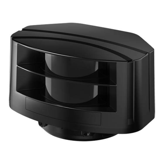
LSE-4A5R2
Laser Scanner
▣ Feature
Activated channel(s) among Ch1 to Ch4
- Monitoring zone setting
- Concentrated monitoring zone setting by channel
Minimum size of the scanning target setting (W×H×L: approx. 5/10/15/20cm per each)
Parameter setting and real-time monitoring by laser scanner program (atLidar)
(Ethernet communication)
Easy parameter setting via the remote control
Emitting property: CLASS1, wavelength band (905nm), max. pulse output power: 75W
Small size (W125×H80.3×L88mm) for various installation environment
Protection structure: IP67 (IEC standard)
Please read "Caution for your safety" in operation
manual before using.
▣ Overview
The laser scanner measures the time (TOF: Time-of-Flight) between radiation and reflection of the laser pulse and the object. It detects
the object distance or obstacles existence.
The laser scanner utilizes for various environment: obstacles detection sensor for subway platform screen door (PSD), industrial door
open/close sensor, security field surveillance sensor, industrial automation field sensor, etc.
Ethernet communication supports to set parameters and real-time monitoring by PC.
Laser radiation
Laser scanner
▣ Manual
For the detail information and instructions, please refer to user manual, and be sure to follow cautions written in the technical descriptions
(catalog, homepage).
Visit our homepage (www.autonics.com) to download manuals.
▣ Laser Scanner Program [atLidar]
atLidar is the laser scanner program that allows installation of the laser scanner,
setting of parameters, and management of monitoring data such as status information.
< System Requirements >
Item
Minimum specifications
System
32bit (×86) or 64bit (×64) processor over 1GHz
Operations
Microsoft Windows 7/8/10
Memory
4GB+
Hard disk
1GB+ of available hard disk space
VGA
Resolution: 1024×768 or higher
※ Laser scanner is connected with atLidar in Ethernet communication.
※ For initial IP address of the laser scanner, refer to the following table.
In order to connect the laser scanner and PC, set IP address of the PC to that of the laser scanner in same subnet.
Item
Laser scanner
Socket
Server
IP address
192.168.0.1
Subnet mask
255.255.255.0
Port
8000
Gateway
192.168.0.2
Reflected laser
Measures the return time
Object
atLidar
Client
IP address of the user PC
255.255.255.0
-
192.168.0.2
Laser Scanner
< atLidar screen >
D-3
Advertisement
Table of Contents

Related Manuals for Autonics LSE-4A5R2


Summary of Contents for Autonics LSE-4A5R2
- Page 1 For the detail information and instructions, please refer to user manual, and be sure to follow cautions written in the technical descriptions (catalog, homepage). Visit our homepage (www.autonics.com) to download manuals. ▣ Laser Scanner Program [atLidar] atLidar is the laser scanner program that allows installation of the laser scanner, setting of parameters, and management of monitoring data such as status information.
-
Page 2: Specifications
LSE-4A5R2 ▣ Specifications LSE-4A5R2 Model Power supply 24VDCᜡ Allowable voltage range 80 to 120% of rated voltage Infrared laser Laser class CLASS 1 Emitting property Wavelength band 905nm Max. pulse output power 75W Angular resolution 0.4° Aperture angle 90° Object reflectivity Min. -
Page 3: Unit Description
Bracket Ø80 4-Ø5 Ethernet cable Ø5, 3m Power, I/O cable Ø5, 5m ▣ Unit Description Laser scanner (LSE-4A5R2) 1. Laser emitter 2. Laser receiver 3. Power, I/O cable 4. Ethernet cable 5. Bracket rotation angle fixing part 6. Bracket tilt angle fixing part ①... -
Page 4: Led Indicator
LSE-4A5R2 ▣ Unit Description Remote control (RMC-LS, sold separately) 1. LOCK/UN-LOCK Function Description Unlock Unlock to press menu key Lock Lock remote control 2. Menu key Function Description Monitoring time Outputs after monitoring time when an obstacle is scanned Scanning target size Sets size of the scanning target (approx. -
Page 5: Connection Cable
Laser Scanner ▣ Connection Cable Power, I/O cable Color Signal Function Brown +V 24VDC Blue 0VDC Yellow OUT1_A Obstacle detection output Green OUT1_B OUT2_A Error status output Gray OUT2_B Black IN_A Output test mode White IN_B ※ The input/output signals can operate in both direction regardless of the polarity. ※... -
Page 6: Installation
LSE-4A5R2 ▣ Installation ① Fix the bracket at the installation position using four allen ② Pass the power, I/O and Ethernet cable through the holes in the wrench bolts (M4, min. 5mm). bracket. Allen wrench bolt 3mm allen wrench ③ Align the mark line of the body and one of the three mark lines of the bracket and turn the bracket clockwise to fix. -
Page 7: Sensor Position
Laser Scanner ▣ Function Setting method Remote control (RMC-LS) Laser scanner program (atLidar) Functions Sensor position Activated channel(s) Monitoring zone width (W), height (H) Concentrated monitoring zone Sensitivity level Minimum size of the scanning target Monitoring time Output Teaching Password Initialization (except password) IP initialization Setting value initialization (except IP) -
Page 8: Sensitivity Level
LSE-4A5R2 ▣ Function Monitoring zone width (W), height (H) Minimum size of the scanning target - Monitoring zone width and height can be set in increments of - The minimum size of the scanning target can be set from OFF, 0.1mm, within the range from 0.5×0.5m to 6×6m. -
Page 9: Troubleshooting
※ If any key is not entered for 1 sec after entering the key, the laser scanner is scanning mode. ▣ Troubleshooting ※Check the normal operation status of LSE-4A5R2 periodically. Error Causes Troubleshooting Supply the power voltage. - Page 10 LSE-4A5R2 ▣ Applications Passenger presence / absence detection of subway Vehicle classification and detection through highway tollgate platform screen door (PSD) Security of store door Security of private house or villa door Prevention of collision by detection of forklift and industrial...
-
Page 11: Cautions During Use
Laser Scanner ▣ Cautions during Use ● Follow instructions in 'Cautions during Use'. Otherwise, it may cause unexpected accidents. ● 24VDC power supply should be insulated and limited voltage/current or Class 2, SELV power supply device. ● After supplying power, the sensor performs self-check for about 10 sec. When self-checking, error occurrence, remote control setting, and teaching, the laser scanner outputs the same as it sensed obstacle.
Need help?
Do you have a question about the LSE-4A5R2 and is the answer not in the manual?
Questions and answers