Table of Contents
Advertisement
Quick Links
TCD210007AB
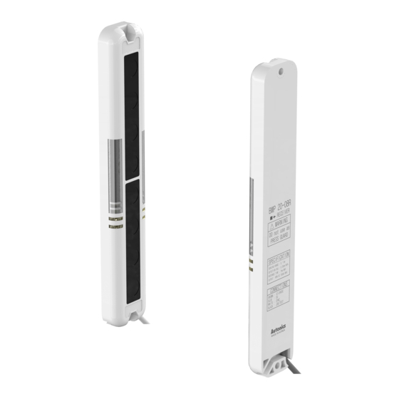
Slim Plastic Single-Beam
Area Sensors
BWP Series
For your safety, read and follow the considerations written in the instruction
manual, other manuals and Autonics website.
The specifications, dimensions, etc. are subject to change without notice for product
improvement. Some models may be discontinued without notice.
Features
• Flat body (13 mm) area sensors with Fresnel lens
• High strength PC / ABS plastic body
• High-speed response time under 7ms
• 4 configurations (optical axis : 8 to 20, detection area : 140 to 380 mm)
• Operation test (emitter stop) function, mutual interference prevention function, Job
indicator ON/FLASHING switch, Light ON/Dark ON operation mode switch
• Bright LED indicators on emitter and receiver
• IP40 protection structure (IEC standard)
ᜢ ᜫ
Safety Considerations
• Observe all 'Safety Considerations' for safe and proper operation to avoid hazards.
• symbol indicates caution due to special circumstances in which hazards may occur.
Warning
Failure to follow instructions may result in serious injury or death.
01. Fail-safe device must be installed when using the unit with machinery that
may cause serious injury or substantial economic loss. (e.g. nuclear power
control, medical equipment, ships, vehicles, railways, aircraft, combustion
apparatus, safety equipment, crime/disaster prevention devices, etc.)
Failure to follow this instruction may result in personal injury, economic loss or
fire.
02. Do not use the unit in the place where flammable/explosive/corrosive gas,
high humidity, direct sunlight, radiant heat, vibration, impact, or salinity
may be present.
Failure to follow this instruction may result in explosion or fire.
03. Do not connect, repair, or inspect the unit while connected to a power
source.
Failure to follow this instruction may result in fire.
04. Check 'Connections' before wiring.
Failure to follow this instruction may result in fire.
05. Do not disassemble or modify the unit.
Failure to follow this instruction may result in fire.
06. This product is not safety sensor and does not observe any domestic nor
international safety standard.
Do not use this product with the purpose of injury prevention or life protection, as
well as in the place where economic loss maybe present.
Caution
Failure to follow instructions may result in injury or product damage.
01. Use the unit within the rated specifications.
Failure to follow this instruction may result in fire or product damage.
02. Use a dry cloth to clean the unit, and do not use water or organic solvent.
Failure to follow this instruction may result in fire.
03. Do not use a load over the range of rated relay specification.
Failure to follow this instruction may result in fire, relay broken, contact melt,
insulation failure or contact failure.
Cautions during Use
• Follow instructions in 'Cautions during Use'. Otherwise, It may cause unexpected
accidents.
• 12 - 24 VDCᜡ power supply should be insulated and limited voltage/current or Class
2, SELV power supply device.
• Use the product, 1 sec after supplying power. When using separate power supply for
the sensor and load, supply power to sensor first.
• When using switching mode power supply to supply the power, ground F.G. terminal
and connect a condenser between 0 V and F.G. terminal to remove noise.
• When connecting a DC relay or other inductive load, remove surge by using diodes
or varistors.
• Wire as short as possible and keep away from high voltage lines or power lines, to
prevent surge and inductive noise.
• This unit may be used in the following environments.
- Indoors (in the environment condition rated in 'Specifications')
- Altitude max. 2,000 m
- Pollution degree 2
- Installation category II
Advertisement
Table of Contents

Related Manuals for Autonics BWP Series


Summary of Contents for Autonics BWP Series
- Page 1 For your safety, read and follow the considerations written in the instruction and connect a condenser between 0 V and F.G. terminal to remove noise. manual, other manuals and Autonics website. • When connecting a DC relay or other inductive load, remove surge by using diodes The specifications, dimensions, etc.
- Page 2 Dimensions • Be sure to install this product by following the usage environment, location, and • Unit: mm, For the detailed drawings, follow the Autonics website. specified ratings. Consider the listed conditions below. • When installing, use M4 bolts for mounting screws and tighten with a torque of - Installation environment and background (reflected light) 2 N m or less.
- Page 3 Check the wiring connection. connection or disconnection LED displays for synchronous line Break of synchronous circuit of Contact Autonics Corp. emitter or receiver Control output line is shorted out. Check the wiring connection. LED displays for over current Over load...
- Page 4 -|Transparent Guide|- Installations Feature Data ■ For direction of installation ■ Parallel shifting characteristic Emitter and receiver should be installed in same up/down direction. Emitter Receiver Emitter Receiver Emitter ■ For reflection from the surface of wall and flat When installing it as below, the light reflected from the surface of wall and flat is not shaded.
- Page 5 -|Transparent Guide|- Sold Separately: Bracket • Unit: mm, For the detailed drawings, follow the Autonics website. • When using the flat bracket or L-shaped bracket, use the protection bracket first. When mounting the protection bracket, it is possible to install the flat / L-shaped bracket, close mounting is available.
Need help?
Do you have a question about the BWP Series and is the answer not in the manual?
Questions and answers