ZURN AquaSense ZTR Series Installation, Operation, Maintenance And Parts Manual
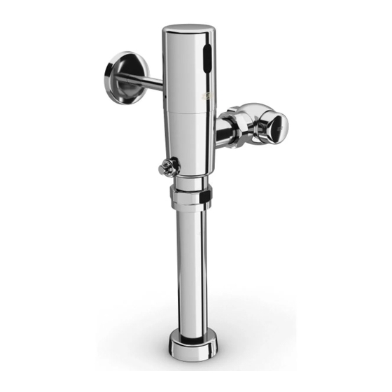
Automatic sensor-operated piston type flushometer for water closets and urinals
Hide thumbs
Also See for AquaSense ZTR Series:
Advertisement
Water Closet Models:
ZTR6200-ONE 1.1 gpf
ZTR6200EV
ZTR6200-WS1 1.6 gpf
Power Options:
Battery (Standard)
-LL (Long Life Battery)
-HW (Hardwired using 7.6 VDC Power Supply Input)
WARNING: Cancer and Reproductive Harm - www.P65Warnings.ca.gov
ADVERTENCIA: Cáncer y daño reproductivo - www.P65Warnings.ca.gov
AVERTISSEMENT: Cancer et effets néfastes sur la reproduction - www.P65Warnings.ca.gov
All goods sold hereunder are warranted to be free from defects in material and factory workmanship for a period of three years from the date of purchase.
Decorative finishes warranted for one year. We will replace at no costs goods that prove defective provided we are notified in writing of such defect and the
goods are returned to us prepaid at Sanford, NC, with evidence that they have been properly maintained and used in accordance with instructions. We shall
not be responsible for any labor charges or any loss, injury or damages whatsoever, including incidental or consequential damages. The sole and exclusive
remedy shall be limited to the replacement of the defective goods. Before installation and use, the purchaser shall determine the suitability of the product for his
intended use and the purchaser assumes all risk and liability whatever in connection therewith. Where permitted by law, the implied warranty of merchantability
is expressly excluded. If the products sold hereunder are "consumer products," the implied warranty of merchantability is limited to a period of three years and
shall be limited solely to the replacement of the defective goods. All weights stated in our catalogs and lists are approximate and are not guaranteed.
NOTICE: READ ENTIRE MANUAL PRIOR TO INSTALLING PRODUCT
1.28 gpf
LIMITED WARRANTY
AquaSense
ZTR Series
Automatic Sensor-Operated Piston
Type Flushometer for Water Closets
and Urinals
Installation, Operation, Maintenance
and Parts Manual
Urinal Models:
ZTR6203-ULF 0.125 gpf
ZTR6203-QRT 0.25 gpf
ZTR6203-EWS 0.5 gpf
ZTR6203-WS1 1.0 gpf
®
Advertisement
Table of Contents

Related Manuals for ZURN AquaSense ZTR Series


Summary of Contents for ZURN AquaSense ZTR Series
- Page 1 AquaSense ® ZTR Series Automatic Sensor-Operated Piston Type Flushometer for Water Closets and Urinals Installation, Operation, Maintenance and Parts Manual Water Closet Models: Urinal Models: ZTR6200-ONE 1.1 gpf ZTR6203-ULF 0.125 gpf ZTR6200EV 1.28 gpf ZTR6203-QRT 0.25 gpf ZTR6200-WS1 1.6 gpf ZTR6203-EWS 0.5 gpf ZTR6203-WS1 1.0 gpf Power Options:...
-
Page 2: Required Tools
ZTR Series Flush Valve Package Contents ZTR6200 ZTR6203 Cast Wall Escutcheon Cast Wall Escutcheon Sweat Kit Sweat Kit Stop Valve Stop Valve Valve Assembly Valve Assembly Vandal Cover Vandal Cover Magic Magic Vacuum Breaker Vacuum Breaker Magnet Magnet Batteries Batteries Vacuum Breaker Vacuum Breaker Tube... -
Page 3: Specifications
Overview: Zurn Aqua-Sense® ZTR Series Flushometer offers two models (closet/urinal) in a variety of flow rates. The ZTR design is a chrome plated brass body with an automatic sensor-operated piston-type valve. The flushometer incorporates a filtered bypass, high back pressure vacuum breaker, adjustable tailpiece, spud coupling, flange for top spud connection and a mechanical override pushbutton (MOB) for alternative flushing methods. - Page 4 Sweat Solder Adapter Installation Instructions - STEP 1 NOTE: Before installation, turn off water supplies to existing fixture and remove flushometer if replacing an existing device. STEP 1.1 STEP 1.2 Measure distance from finished wall to the center line of the fixture Slide threaded sweat solder adapter onto water supply pipe until spud.
- Page 5 Flush Valve Installation - STEP 3 STEP 3.1 STEP 3.2 Prior to attaching flush valve to control stop(A) inspect and verify Lubricate O-ring with water if necessary and carefully insert flush that the O-ring (C) is located within the O-ring groove at the tailpiece. valve tailpiece into the control stop valve to ensure O-ring remains Ensure the locking nut (D) and locking snap ring (E) are also present seated.
- Page 6 Battery Installation (Applies to battery and -LL versions only) - STEP 5A STEP 5A.1 STEP 5A.2 Remove sealed battery housing from sensor cap and remove top Connect sealed battery housing to sensor lens via RED connectors of sealed battery housing by loosening the knurled screw by hand by aligning arrows and pressing together.
- Page 7 Connect ZTR-HW directly to HW6 Power Converter. (Recommended if one to two ZTR flush valves are powered by one HW6.) STEP 5B.2 STEP 5B.3 Cut RED power connector from end of power supply cable not Secure RED wire to Positive (+) and BLACK wire to Negative (-) connected to the Sensor Cap and strip back the wire insulation by screw terminals on HW6.
- Page 8 Metal Sensor Cap Retrofit Installation Instructions STEP 6.1 STEP 6.2 Remove vandal-resistant cover with allen wrench from control Press and hold the manual override button for 3 seconds to stop (if present) and turn control stop clockwise to turn off the release any residual pressure.
- Page 9 STEP 6.7 STEP 6.8 Note socket screw pockets in the ring insert and place over Ensure ring insert set screws align with valve body holes shown remaining 2 socket screws See Figure 19. in Figure 20. Hand start the 4 new sockets screws(included) into the ring insert.
- Page 10 STEP 6.11 (For Hardwired Only) STEP 6.12 Route 10’ power supply cable throught the wall escutcheon, wire Align set screw hole in sensor cap with key way in ring insert and supply tube, and the opening on the back of the metal sensor place sensor cap on valve body.
- Page 11 STEP 1.1 Place the Zurn MagicMagnet® (supplied) against the cap at the lower right corner of the Zurn logo under the sensor lens. Hold in place until the valve automatically flushes and the red LED light flashes two(2) times. Remove Magic Magnet from flush valve.
-
Page 12: Troubleshooting Guide
Move DIP switch to desired posi- DIP switch settings Configuration changes to DIP switches tion. Reconnect power, allowing 30 sec- onds to complete power up sequence. For futher assistance with troubleshooting, visit http://www.zurn.com/ FV541 Rev. T 7/18/2018 Page 12... - Page 13 Sweat solder kit, Items 25-29 P6003-YBYC ZURN INDUSTRIES, LLC 5900 Elwin Buchanan Drive, Sanford, NC U.S.A. 27330, Ph. 1-800-997-3876, Fax 919-775-3541 In Canada: ZURN INDUSTRIES LIMITED 7900 Goreway Drive, Unit 10, Brampton, Ontario L6T 5W6, Ph. 905-405-8272, Fax 905-405-1292 Rev. T Date: 7/18/2018 C.N.
- Page 14 Sweat solder kit, Items 25-29 P6003-YBYC ZURN INDUSTRIES, LLC 5900 Elwin Buchanan Drive, Sanford, NC U.S.A. 27330, Ph. 1-800-997-3876, Fax 919-775-3541 In Canada: ZURN INDUSTRIES LIMITED 7900 Goreway Drive, Unit 10, Brampton, Ontario L6T 5W6, Ph. 905-405-8272, Fax 905-405-1292 Rev. T Date: 7/18/2018 C.N.
Need help?
Do you have a question about the AquaSense ZTR Series and is the answer not in the manual?
Questions and answers