
Subscribe to Our Youtube Channel
Related Manuals for SIGMATEK ETT 731


Summary of Contents for SIGMATEK ETT 731
- Page 1 ETT 731 Build-in Terminal Touch Technical Manual Date of creation: 10.02.2014 Version date: 05.12.2019 Article number: 07-230-731-E...
- Page 2 (print, photocopy, microfilm or in any other process) without the express permission. We reserve the right to make changes in the content without notice. The SIGMATEK GmbH & Co KG is not responsi- ble for technical or printing errors in the handbook and assumes no responsibility for damages that occur through...
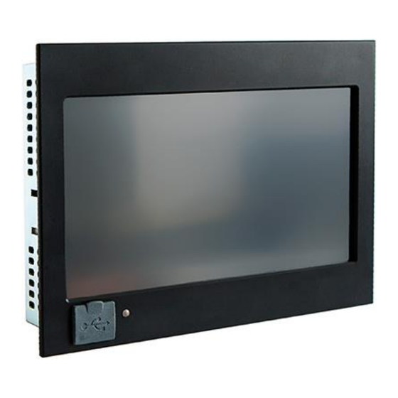
- Page 3 ETT 731 Build-in Terminal Touch ETT 731 The ETT 731 is an intelligent terminal for programming and visualization of automated pro- cesses. Process diagnostics as well as operating and monitoring automated procedures are simplified using this terminal. A resistive touch screen serves as the input medium for process data and parameters. The output is shown on a 7"...
-
Page 4: Table Of Contents
ETT 731 BUILD-IN TERMINAL TOUCH Contents Technical Data ................ 4 Performance Data ................. 4 Electrical Requirements ............... 5 Terminal ..................5 Environmental Conditions ............5 7” WVGA Display incl. Touch ............6 Miscellaneous ................6 Mechanical Dimensions ............7 Connector Layout ..............8 Front: .................... - Page 5 BUILD-IN TERMINAL TOUCH ETT 731 Shielding ..................19 ESD Protection ................19 USB Interface Connections ............19 CAN Bus Setup ..............20 CAN Bus Station Number ............20 Number of CAN Bus Participants ..........20 CAN Bus Data Transfer Rate ............. 20 CAN Bus Termination ............
-
Page 6: Technical Data
ETT 731 BUILD-IN TERMINAL TOUCH Technical Data Performance Data Processor EDGE2-Technology Processor cores Internal cache 32-kbyte L1 Instruction Cache 32-kbyte L1 Data Cache 512-kbyte L2 Cache Internal program and 256-Mbytes data memory (DDR3 RAM) Internal remnant 256-kbyte SRAM (battery buffered) -
Page 7: Electrical Requirements
BUILD-IN TERMINAL TOUCH ETT 731 Electrical Requirements Supply voltage typically +24 V DC (+18-30 V DC) Current consumption of power typically 210 mA maximum 360 mA supply at +24 V (without externally connected devices) (with externally connected devices) Current consumption of... -
Page 8: 7" Wvga Display Incl. Touch
ETT 731 BUILD-IN TERMINAL TOUCH 7” WVGA Display incl. Touch Type 7" TFT LCD color display Resolution WVGA 800 x 480 Pixel Color depth 16-bit RGB (65K colors) LCD mode normal white LCD Polarizer transmissive Pixel size 0.1926 mm x 0.1790 mm... -
Page 9: Mechanical Dimensions
BUILD-IN TERMINAL TOUCH ETT 731 Mechanical Dimensions 05.12.2019 Page 7... -
Page 10: Connector Layout
ETT 731 BUILD-IN TERMINAL TOUCH Connector Layout Front: X7: USB 2.0 (Type A) Function +5 V It should be noted that many of the USB devices on the market do not comply with USB specifications; this can lead to device malfunctions. It is also possible that these devices will not be detected at the USB port or function correctly. -
Page 11: Backside
BUILD-IN TERMINAL TOUCH ETT 731 Backside X1: CAN 1 (6-pin Weidmüller plug) Function CAN A (CAN LOW) CAN B (High) CAN A (CAN LOW) CAN B (High) n.c. n.c. = do not use 05.12.2019 Page 9... - Page 12 ETT 731 BUILD-IN TERMINAL TOUCH X2: CAN 2 (6-pin Weidmüller plug) Function CAN A (CAN LOW) CAN B (High) CAN A (CAN LOW) CAN B (HIGH) n.c. X3: USB 2.0 (Type A) Function +5 V X4: RS232 (D-Sub) Function X5: Ethernet 10/100 (RJ45)
-
Page 13: Applicable Connectors
By configuring the packet filter (Firewall or Router) accordingly however, it is possible to connect a network with SIGMATEK hardware to a third party network without trig- gering the problems mentioned above. -
Page 14: Cooling
ETT 731 BUILD-IN TERMINAL TOUCH Cooling The terminal's power loss can reach up to 7.5 Watts. To ensure the necessary air circula- tion for cooling, the following mounting instructions must be followed! Mounting Instructions The following distance from the housing should be maintained:... - Page 15 BUILD-IN TERMINAL TOUCH ETT 731 A mounting position of 60° to 120° is also required. 05.12.2019 Page 13...
-
Page 16: Buffer Battery
Buffer Battery The exchangeable buffer battery ensures that the clock time (RTC) and SRAM data of the ETT 731 are preserved in the absence of a supply voltage. A lithium battery is installed at the manufacturer. After delivery of the HZS 713-H and a storage time of one year, the lifespan of the battery reaches 10 years, if you make sure, that the device mainly is in operation (supply voltage is on). -
Page 17: Exchanging The Battery: Option 1
BUILD-IN TERMINAL TOUCH ETT 731 Exchanging the Battery: Option 1 1. Disconnect the ETT 731 supply. 2. Open the seven locking screws (Torx) on the back of the terminal with a Tx9 screwdriver. 05.12.2019 Page 15... - Page 18 6. Insert the new battery with the correct polarity (plus side facing the back of the terminal). Lay the sticker lifted in step 5 back over the battery, disconnect the supply, place the back panel of the terminal back on and tighten the locking screws. 7. Connect the ETT 731 supply. Page 16 05.12.2019...
-
Page 19: Exchanging The Battery: Option 2
1. The SRAM data are saved in the Flash using the CLI command SRAM Save. ATTENTION: If the data are not first saved, the settings of the terminal are lost. 2. Disconnect the ETT 731 supply. 3. Loosen the seven locking screws (Torx) on the back of the terminal with a Tx9 screwdriver. - Page 20 ETT 731 BUILD-IN TERMINAL TOUCH 4. Lift rear panel of the terminal: Sticker 5. Lift the sticker and battery from the battery holder using the strap. 6. Insert the new battery with the correct polarity (plus side facing the back of the terminal).
-
Page 21: Wiring Guidelines
BUILD-IN TERMINAL TOUCH ETT 731 Wiring Guidelines Ground The terminal must be connected to ground through the assembly on the control cabinet or over the connection provided. It is important to create a low-ohm ground connection, only then can error-free operation be guaranteed. The ground connection should have a maxi- mum cross section and the largest (electrical) surface possible. -
Page 22: Can Bus Setup
ETT 731 BUILD-IN TERMINAL TOUCH CAN Bus Setup This section explains how to correctly configure the CAN bus. The following parameters must first be set: Station number and data transfer rate. CAN Bus Station Number Each CAN bus station is assigned its own station number. With this station number, data can be exchanged with other stations connected to the bus. -
Page 23: Can Bus Termination
BUILD-IN TERMINAL TOUCH ETT 731 CAN Bus Termination In a CAN bus system, both end modules must be terminated. This is necessary to avoid transmission errors caused by reflections in the line. The termination is made by an internal 120R resistor between CAN-A (LOW) and CAN-B (HIGH). -
Page 24: Process Diagram
ETT 731 BUILD-IN TERMINAL TOUCH 10 Process Diagram Page 22 05.12.2019... -
Page 25: Status And Error Messages
BUILD-IN TERMINAL TOUCH ETT 731 11 Status and Error Messages Status and error messages are displayed in the LASAL Class software status test. POINTER or CHKSUM messages can also be shown on the terminal screen. Number Message Definition Cause/Solution RUN RAM... - Page 26 ETT 731 BUILD-IN TERMINAL TOUCH WATCHDOG The program was interrupted via the Possible Causes: watchdog logic. User program interrupts blocked over a longer period of time (STI command forgotten) Programming error in a hardware interrupt. INB, OUTB, INW, OUTW instruc- tions used incorrectly.
- Page 27 BUILD-IN TERMINAL TOUCH ETT 731 STOP BRKPT The CPU was stopped by a breakpoint Info in the program. CPU STOP The CPU was stopped by the program- Info ming software. INT ERROR The CPU has triggered a false interrupt Cause:...
- Page 28 OP INSTALLED The operating system has been rein- Info stalled. OS TOO LONG The operating system cannot be loaded; Restart; report error to SIGMATEK. too little memory. NO OPERATING Boot loader message. Restart; report error to SIGMATEK. SYSTEM No operating system found in RAM.
- Page 29 An error has occurred during a floating- ERROR point operation. DIAS-RISC-ERROR Error from the Intelligent DIASMaster. Restart; report error to SIGMATEK. INTERNAL ERROR An internal error has occurred, all appli- Restart; report error to SIGMATEK. cations are stopped. FILE ERROR An error has occurred during a file operation.
- Page 30 ETT 731 BUILD-IN TERMINAL TOUCH C-DIAS ERROR A connection error with a C-DIAS mod- Cause: ule has occurred. The cause of the error is docu- mented in the log file Solution: This depends on the cause S-DIAS ERROR A connection error with a S-DIAS mod- Possible causes: ule has occurred.
- Page 31 BUILD-IN TERMINAL TOUCH ETT 731 C_UNKNOWN_CID An unknown object from a stand-alone or embedded object, or an unknown base class was detected. C_UNKNOWN_CONSTR The operating system class cannot be created; the operating system is proba- bly wrong. C_UNKNOWN_OBJECT Indicates an unknown object in an interpreter program;...
- Page 32 ETT 731 BUILD-IN TERMINAL TOUCH LSL LOAD CONTINUE PRERUN The application is started. PRERESET The application is ended. CONNECTION BREAK Page 30 05.12.2019...
-
Page 33: Display "Burn-In" Effect
BUILD-IN TERMINAL TOUCH ETT 731 12 Display “Burn-In” Effect The “Burn-In” effect describes a pattern burned into the display after displaying the same contents over a longer period of time (e.g. a single screen). This effect is also described mostly as “image sticking”, “memory effect/sticking” or “ghost image”. -
Page 34: Cleaning The Touch Screen
ETT 731 BUILD-IN TERMINAL TOUCH 13 Cleaning the Touch Screen CAUTION! Before cleaning the touch screen, the terminal must first be turned off to avoid unin- tentionally triggering functions or commands! ATTENTION! Avant de nettoyer l'écran tactile, le terminal doit d'abord être éteint afin d’éviter un déclanchement involontaire des commandes! - Page 35 BUILD-IN TERMINAL TOUCH ETT 731 Documentation Changes Change date Affected page(s) Chapter Note 27.02.2014 Added number of pixels in table 16.04.2014 3.2 Status LED Changed LED description 8.1 CAN Bus Station Number Changed text 8.2 Number of CAN Bus Partici-...
- Page 36 ETT 731 BUILD-IN TERMINAL TOUCH Page 34 05.12.2019...
Need help?
Do you have a question about the ETT 731 and is the answer not in the manual?
Questions and answers