
Related Manuals for SIGMATEK ETT 1034


Summary of Contents for SIGMATEK ETT 1034
- Page 1 ETT 1034 Build-in Touch Terminal Technical Manual Date of creation: 19.02.2019 Version date: 19.02.2019 Article number: 01-230-1034-E...
- Page 2 (print, photocopy, microfilm or in any other process) without express permission. We reserve the right to make changes in the content without notice. SIGMATEK GmbH & Co KG is not responsible for technical or printing errors in this handbook and assumes no responsibility for damages that occur through its...
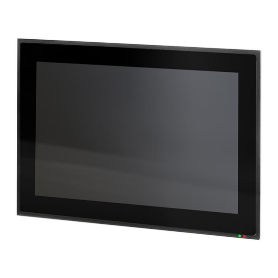
- Page 3 ETT 1034 Build-in Touch Terminal ETT 1034 The ETT 1034 is an intelligent panel for visualizing, operating and monitoring automated pro- cesses. A capacitive touch screen serves as the input medium for process data and parameters. The output is shown on a 10.1" TFT color display.
-
Page 4: Table Of Contents
ETT 1034 BUILD-IN TOUCH TERMINAL Contents Introduction ................5 Target Group/Purpose of this Manual ........5 Important Reference Documentation ......... 5 Contents of Delivery ..............5 Basic Safety Guidelines ............6 Symbols Used ................6 Disclaimer ..................7 General Safety Guidelines ............8 Guidelines.................. - Page 5 BUILD-IN TOUCH TERMINAL ETT 1034 Bottom Connections..............17 5.1.1 X1: Supply (4-pin Phoenix RM 3.5) ........... 17 5.1.2 X2: Ethernet 2 10/100/1000 (RJ45) ..........17 5.1.3 X3: Ethernet 1 10/100 (RJ45) ............17 5.1.4 X4: microSD Card ................18 5.1.5 X5: USB 2.0 (Type A) ...............
- Page 6 ETT 1034 BUILD-IN TOUCH TERMINAL 11 Cleaning the Touch Screen ...........29 12 Buffer Battery .................30 12.1 Exchanging the Battery .............. 31 12.1.1 Without Supply .................. 31 12.1.2 With Active Supply ................33 13 Maintenance ................34 13.1 Maintenance ................34 13.1.1 Calibrating the Touch Screen ............
-
Page 7: Introduction
BUILD-IN TOUCH TERMINAL ETT 1034 Introduction Target Group/Purpose of this Manual This manual contains all information required for operating the ETT 1034. This manual is intended for: • Project planners • Technicians • Configurators/commissioning engineers • Machine operators • Maintenance/test technicians General knowledge of automation technology is required. -
Page 8: Basic Safety Guidelines
ETT 1034 BUILD-IN TOUCH TERMINAL Basic Safety Guidelines Symbols Used The following symbols are used in the operator documentation for warning and danger mes- sages, as well as informational notes: DANGER Identifies an immediate danger with high risk, which will lead to immediate death or serious injury if not avoided. -
Page 9: Disclaimer
Please thoroughly read the corresponding data sheets, operating instructions and this system handbook before handling a product. SIGMATEK GmbH & Co KG is not liable for damages caused through non-compliance with these instructions or applicable regulations. The general and special safety instructions described in the following sec- tions, as well as technical regulations, must therefore be observed. -
Page 10: General Safety Guidelines
Operate the unit with devices and accessories approved by SIGMATEK only. CAUTION Handle the device with care and do not drop or let fall. - Page 11 BUILD-IN TOUCH TERMINAL ETT 1034 In addition, the Safety Guidelines in the other sections of these instructions must be observed. These instructions are visually emphasized by symbols. The module complies with EN 61131-2. In combination with a machine, the machine builder must comply with EN 60204-1 standards.
-
Page 12: Guidelines
BUILD-IN TOUCH TERMINAL Guidelines The panel was constructed in compliance with European Union guidelines. 2.4.1 EU Conformity Declaration CE Declaration of Conformity The ETT 1034 conforms to the following European guidelines: • 2014/35/EU Low-voltage guideline • 2014/30/EU “Electromagnetic Compatibility” (EMC guideline) •... -
Page 13: Technical Data
BUILD-IN TOUCH TERMINAL ETT 1034 Technical Data Performance Data Processor EDGE2 Technology Processor cores Internal cache 32-kbyte L1 Instruction Cache 32-kbyte L1 Data Cache 512-Kbyte L2 Cache Internal program and data 1-Gbyte DDR3 memory (RAM) Internal remnant data 512-kbyte SRAM (battery buffered) -
Page 14: Electrical Requirements
ETT 1034 BUILD-IN TOUCH TERMINAL Electrical Requirements Supply voltage typically +24 V DC (+18-30 V DC) Current consumption of (+24 V) typically 600 mA maximum 750 mA power supply (without external devices con- (with external devices connected) nected) Inrush current with 24 V/10 A maximum 1.5 A (for 15 ms, load-dependent) -
Page 15: Control Unit
BUILD-IN TOUCH TERMINAL ETT 1034 Control Unit Touch panel projective capacitive touch panel Surface front plate: 1.1 mm glass (touch screen) in black anodized aluminum frame Cleaning see chapter 11. A projective capacitive touch screen is built into the panel, with which 10- finger input, Zoom and gesture functions can be implemented. -
Page 16: Minimum Distance Between Operating Elements For Multi- Touch Applications
ETT 1034 BUILD-IN TOUCH TERMINAL Minimum Distance between Operating Elements for Multi-touch Appli- cations To guarantee smooth operation with multitouch applications, buttons and control elements that should be operated at the same time must have the minimum distance shown below (depending on the estimated touch point). -
Page 17: Environmental Conditions
BUILD-IN TOUCH TERMINAL ETT 1034 Environmental Conditions Storage temperature -10 ... +70 °C Environmental temperature 0 ... +50 °C Humidity 10-95 %, non-condensing Installation altitude above sea 0-2000 m without derating, level > 2000 m with derating of the maximum environment temperature by 0.5 °C... -
Page 18: Mechanical Dimensions
ETT 1034 BUILD-IN TOUCH TERMINAL Mechanical Dimensions Dimensions 264 x 183 x 48 mm (W x H x D) Material front plate: 1.1 mm glass (touch screen) in black anodized aluminum frame housing: sheet steel Weight typically 1.5 kg Page 16... -
Page 19: Interfaces
BUILD-IN TOUCH TERMINAL ETT 1034 Interfaces Bottom Connections 5.1.1 X1: Supply (4-pin Phoenix RM 3.5) Function +24 V DC +24 V DC 5.1.2 X2: Ethernet 2 10/100/1000 (RJ45) Function 5.1.3 X3: Ethernet 1 10/100 (RJ45) Function n.c. n.c. n.c. n.c. -
Page 20: X4: Microsd Card
BUILD-IN TOUCH TERMINAL Problems can arise if a control is connected to an IP network, which contains devices that are not running with a SIGMATEK operating system. With such devices, Ethernet packets could be sent to the control with such a high frequency (i.e. -
Page 21: X5: Usb 2.0 (Type A)
BUILD-IN TOUCH TERMINAL ETT 1034 5.1.5 X5: USB 2.0 (Type A) Function +5 V, I = 500 mA out, max. It should be noted that many of the USB devices on the market do not comply with USB specifications; this can lead to device malfunctions. It is also possible that these devices will not be detected at the USB port or function correctly. -
Page 22: Side Connection
ETT 1034 BUILD-IN TOUCH TERMINAL Side Connection Page 20 19.02.2019... -
Page 23: X6: Usb 2.0 (Type Mini B)
BUILD-IN TOUCH TERMINAL ETT 1034 5.3.1 X6: USB 2.0 (Type Mini B) USB device for service purposes and online USB for LasalClass Function +5 V, I = 500 mA out max. Applicable Connectors 4-pin Phoenix plug with spring terminal FK-MCP 1.5/ 4-ST-3.5... -
Page 24: Cooling
ETT 1034 BUILD-IN TOUCH TERMINAL Cooling The power loss in the ETTs can reach up to 19 Watts. To ensure the necessary air circulation for cooling, the following mounting instructions must be followed! Mounting Instructions During installation, caution must be taken to ensure that the aluminum front is not damaged. -
Page 25: Restricted Space Around Rear Trimming
BUILD-IN TOUCH TERMINAL ETT 1034 Restricted Space Around Rear Trimming A restricted area of 15 mm around the terminal must be ensured. This is required to exchange the module when necessary, without having to remove the entire device. 19.02.2019 Page 23... -
Page 26: Required Cutout For Mounting The Terminal
ETT 1034 BUILD-IN TOUCH TERMINAL Required Cutout for Mounting the Terminal Mounting Position Note the mounting position of 60-120°. The specified installation distances may be reduced if appropriate measures and technical precautions are taken to dissipate the corresponding waste heat. -
Page 27: Wiring Guidelines
BUILD-IN TOUCH TERMINAL ETT 1034 Wiring Guidelines Protective Earth Connection WARNING The terminal must be grounded to protective earth (PE) via the M3 threaded bolts. In addition, ensure that when installing into the control cabinet, a large grounding surface is provided. It is essential to establish a low-Ohm connection to ground to ensure error-free function. -
Page 28: Esd Protection
ETT 1034 BUILD-IN TOUCH TERMINAL ESD Protection Typically, USB devices (keyboard, mouse...) are not equipped with shielded cables. These devices are disrupted by electrostatic discharge and in some instances, no longer function. Généralement, les périphériques USB (clavier, souris...) ne sont pas équipés de câbles blindés. -
Page 29: Status Leds
BUILD-IN TOUCH TERMINAL ETT 1034 Status LEDs Color Definition green DCOK Error The status LEDs can be controlled via the application. With standard settings within an appli- cation or after starting the operating system, the LEDs respond as follows: Turning on the supply DCOK lights green In the CLI, while processing the autoexec.lsl until the application... -
Page 30: Display „Burn-In" Effect
ETT 1034 BUILD-IN TOUCH TERMINAL 10 Display „Burn-In“ Effect The “Burn-In” effect describes a pattern burned into the display after displaying the same contents over a longer period of time (e.g. a single screen). This effect is also described mostly as “image sticking”, “memory effect/sticking” or “ghost image”. -
Page 31: Cleaning The Touch Screen
BUILD-IN TOUCH TERMINAL ETT 1034 11 Cleaning the Touch Screen WARNING Before cleaning the touch screen, the HGW must be turned off in order to prevent triggering functions or commands unintentionally! Avant de nettoyer l'écran tactile, le HGW doit être éteint afin d'éviter tout déclenchement involontaire de fonctions ou de commandes! -
Page 32: Buffer Battery
If the Buffer Battery is empty, it should be replaced by an identical Buffer Battery. Use only Buffer Battery from RENATA with the number: CR2032 The SIGMATEK order number can be found below in the chapter Accesso- ries. If the battery voltage is located between both thresholds of the monitoring switch, the battery can be detected as good during operation, but as low after turning off and on. -
Page 33: Exchanging The Battery
BUILD-IN TOUCH TERMINAL ETT 1034 12.1 Exchanging the Battery 12.1.1 Without Supply Turn of the device supply. After turning off the supply, three minutes of buffering is pro- vided to replace battery. i. We recommend to first save the SRAM data to the microSD card... - Page 34 ETT 1034 BUILD-IN TOUCH TERMINAL Rotate the cover in the direction of the arrow shown below. Using the strap, remove the battery from the holder. Install the new battery with the correct polar- ity. Close the battery cover. Tighten the fastening screws.
-
Page 35: With Active Supply
BUILD-IN TOUCH TERMINAL ETT 1034 12.1.2 With Active Supply If the battery is exchanged when an active supply is connected, there is no time limit. Prefer- ably however, save the SRAM data on the microSD card in case the power supply is inter- rupted during the exchange. -
Page 36: Maintenance
ETT 1034 BUILD-IN TOUCH TERMINAL 13 Maintenance During maintenance as well as servicing, the safety instructions from chapter 2must be observed. 13.1 Maintenance This product was constructed for low-maintenance operation. 13.1.1 Calibrating the Touch Screen The touch screen is calibrated at the factory. You should therefore only recalibrate the touch screen when press-point changes are noticed. -
Page 37: Process Diagram
BUILD-IN TOUCH TERMINAL ETT 1034 14 Process Diagram 19.02.2019 Page 35... -
Page 38: Status And Error Messages
ETT 1034 BUILD-IN TOUCH TERMINAL 15 Status and Error Messages Status an error messages are displayed in the LASAL CLASS software status test. POINTER or CHKSUM messages are shown on the terminal screen. Number Message Definition Cause/solution RUN RAM The user program is currently running in Info RAM. - Page 39 BUILD-IN TOUCH TERMINAL ETT 1034 WATCHDOG The program was interrupted via the Possible Causes: watchdog logic. User program interrupts blocked over a longer period of time (STI command forgotten). Programming error in a hardware interrupt. INB, OUTB, INW, OUTW instruc- tions used incorrectly.
- Page 40 ETT 1034 BUILD-IN TOUCH TERMINAL STOP BRKPT The CPU was stopped by a breakpoint in Info the program. CPU STOP The CPU was stopped by the program- Info ming software. INT ERROR The CPU has triggered a false interrupt Causes:...
- Page 41 OP INSTALLED The operating system has been rein- Info stalled. OS TOO LONG The operating system cannot be loaded; Restart, report error to SIGMATEK. too little memory. NO OPERATING Boot loader message. Restart, report error to SIGMATEK. SYSTEM No operating system found in RAM.
- Page 42 An error has occurred during a floating- ERROR point operation. DIAS-RISC-ERROR Error from the Intelligent DIAS Master. Restart, report error to SIGMATEK. INTERNAL ERROR An internal error has occurred, all appli- Restart, report error to SIGMATEK. cations are stopped. FILE ERROR An error has occurred during a file opera- tion.
- Page 43 BUILD-IN TOUCH TERMINAL ETT 1034 C-DIAS ERROR A connection error with a C-DIAS module Cause: has occurred. The cause of the error is docu- mented in the log file Solution: This depends on the cause S-DIAS ERROR A connection error with an S-DIAS Possible Causes: module has occurred.
- Page 44 ETT 1034 BUILD-IN TOUCH TERMINAL C_UNKNOWN_CID An unknown object from a stand-alone or embedded object, or an unknown base class was detected. C_UNKNOWN_CONSTR The operating system class cannot be created; the operating system is probably wrong. C_UNKNOWN_OBJECT Indicates an unknown object in an inter- preter program;...
- Page 45 BUILD-IN TOUCH TERMINAL ETT 1034 CONTINUE PRERUN The application is started. PRERESET The application is ended. CONNECTION BREAK 19.02.2019 Page 43...
-
Page 46: Modularity
ETT 1034 BUILD-IN TOUCH TERMINAL 16 Modularity Through its modular construction, the device is prepared for a simple exchange of compo- nents. This makes it possible in the future, to vary the touch panel (TP) or panel interface module (PIM), and adapt to actual system requirements. -
Page 47: Disassembly
BUILD-IN TOUCH TERMINAL ETT 1034 To mount PIM with TP, follow the steps below: Ensure that an ESD-compliant working method is followed (ESD armband, ESD clothing). Disconnect the PIM as well as the TP from voltage. Place the TP flat on its back. -
Page 48: Accessories
ETT 1034 BUILD-IN TOUCH TERMINAL 17 Accessories Use only batteries from RENATA with the number: CR2032 17.1 Buffer Battery Label Order Number Renata CRC2032 (235 mAh) 01-690-055 18 Transport/Storage This device contains sensitive electronics. During transport and storage, high mechanical stress must therefore be avoided. - Page 49 BUILD-IN TOUCH TERMINAL ETT 1034 Documentation Changes Change date Affected page(s) Chapter Note 19.02.2019 Page 47...
- Page 50 ETT 1034 BUILD-IN TOUCH TERMINAL Page 48 19.02.2019...
Need help?
Do you have a question about the ETT 1034 and is the answer not in the manual?
Questions and answers