Table of Contents
Advertisement
Quick Links
Advertisement
Table of Contents

Related Manuals for SIM Tech SIMCom SIM7100-PCIE


Summary of Contents for SIM Tech SIMCom SIM7100-PCIE
- Page 1 SIM7100-PCIE_Hardware Design_V1.05...
-
Page 2: General Notes
Smart Machine Smart Decision Document Title SIM7100-PCIE Hardware Design Version 1.05 Date 2017-02-24 Status Released Document SIM7100-PCIE_Hardware_Design_V1.05 Control ID General Notes SIMCom offers this information as a service to its customers to support the application and engineering efforts that use the products designed by SIMCom. The information provided is based on the requirements specifically from the customers. -
Page 3: Table Of Contents
Smart Machine Smart Decision Contents General Notes ................................2 Copyright .................................. 2 Contents ..................................3 Table Index ................................5 Figure Index ................................6 Version History ................................ 7 Introduction ............................... 8 Product Outline ............................8 Hardware Interface Overview ........................9 Hardware Block Diagram ........................10 Functional Overview .......................... - Page 4 Smart Machine Smart Decision Recommended Operating Conditions ..................... 36 Operating Mode ............................36 5.3.1 Operating Mode ..........................36 5.3.2 Power saving mode ..........................37 5.3.3 Sleep mode ............................37 5.3.4 Minimum functionality mode......................37 Current Consumption ..........................38 Electro-Static Discharge ......................... 40 Product label ..............................
- Page 5 Smart Machine Smart Decision Table Index TABLE 1: SIM7100-PCIE SERIES FREQUENCY BANDS .................... 8 TABLE 2: SIM7100-PCIE KEY FEATURES ........................10 TABLE 3: PCI EXPRESS MINI CARD CONNECTOR PIN DESCRIPTION ............... 12 TABLE 4: RECOMMENDED 3.3V POWER SUPPLY CHARACTERISTICS ............. 15 TABLE 5: PERST# PIN ELECTRONIC CHARACTERISTIC ..................
- Page 6 Smart Machine Smart Decision Figure Index FIGURE 1: SIM7100-PCIE BLOCK DIAGRAM ......................10 FIGURE 2: SIM7100-PCIE PIN OUT DIAGRAM ......................12 FIGURE 3: DIMENSIONS OF SIM7100-PCIE (UNIT: MM) ..................14 FIGURE 4: PERST# REFERENCE CIRCUIT ........................ 15 FIGURE 5: W_DISABLE# REFERENCE CIRCUIT ...................... 16 FIGURE 6: LED_WWAN# REFERENCE CIRCUIT ......................
-
Page 7: Version History
Smart Machine Smart Decision Version History Date Version Description of change Author 2015-04-07 1.01 Origin Ye Haibing Xing Lei Update the frequency band information of SIM7100CE, 2016-03-24 1.02 Ma Honggang SIM7100V Update the date of current consumption 2016-09-28 1.03 Add the label picture of SIM7100-PCIEA Zhang Xiaojun Renew the codec from WM8960 to NAU8810 2016-11-09... -
Page 8: Introduction
This document describes the electronic specifications, RF specifications, interfaces, mechanical characteristics and testing results of the SIMCom SIM7100-PCIE modules. With the help of this document and other related software application notes/user guides, users can understand and use SIM7100-PCIE modules to design and develop applications quickly. -
Page 9: Hardware Interface Overview
Smart Machine Smart Decision LTE TDD B38 LTE TDD B39 LTE-TDD LTE TDD B40 LTE TDD B41 GNSS GLONASS *Note: If Analog audio is needed, please consult our sales staff, for more information . -
Page 10: Hardware Block Diagram
Smart Machine Smart Decision Hardware Block Diagram The following figure is SIM7100-PCIE hardware block diagram. Main Antenna Aux Antenna GNSS Antenna EAR_N EAR_P Codec MIC_N DDR(1GB) GNSS MIC_P GSM/WCDMA WCDMA NAND(2GB) /TD/LTE /LTE RF FEM RF FEM WAKE# Processor Transceiver USIM Qualcomm W_DISABLE#... - Page 11 Smart Machine Smart Decision HSPA+: 5.76 Mbps(UL), 42 Mbps(DL) TD-HSDPA/HSUPA: 2.2 Mbps(UL), 2.8 Mbps(DL) CDMA EVDO:Rev-0,Rev-A, Rev-B LTE Category 3 - 100 Mbps (DL) LTE Category 3 - 50 Mbps (UL) GSM/UMTS/LTE main antenna. Antenna UMTS/LTE auxiliary antenna.
-
Page 12: Package Information
Smart Machine Smart Decision 2 Package Information Pin Out Diagram Figure 2: SIM7100-PCIE Pin Out Diagram PCI Express Mini Card Connector Pin Description Table 3: PCI Express Mini Card Connector Pin Description Pin name Pin number Description Comment Power supply 2,24,39,41,52 3.3V Power supply for module 4,9,15,18,21,... - Page 13 Smart Machine Smart Decision USIM card interface Power output for USIM card, its output Voltage USIM_VDD depends on USIM card type automatically. Its output current is up to 50mA. USIM Card data I/O, which has been pulled up USIM_DATA via a 20KR resistor to USIM_VDD internally. Do not pull it up or down externally.
-
Page 14: Package Dimensions
Smart Machine Smart Decision Optional: Receiver negative output If unused, keep W_DISABLE# RF Control Input open. Network Status Indication output If unused, keep LED_WWAN# open. 6,23,25,28,31 No connection Keep open ,33,48 Package Dimensions Figure 3: Dimensions of SIM7100-PCIE (Unit: mm) SIM7100-PCIE_Hardware_Design_V1.05 2017-02-24... -
Page 15: Interface Application
Smart Machine Smart Decision 3 Interface Application Power Supply The recommended power supply voltage of SIM7100-PCIE is 3.3V. Table 4: Recommended 3.3V Power Supply Characteristics Symbol Parameter Type Unit Power supply voltage Supply current capability 2000 PERST# SIM7100-PCIE can be reset by pulling the PERST# pin down to ground. The PERST# pin has been pulled up with a 40KΩ... -
Page 16: W_Disable
Smart Machine Smart Decision W_DISABLE# The W_DISABLE# pin can be used to control SIM7100-PCIE to enter or exit the Flight mode. In Flight mode, the RF circuit is closed to prevent interference with other equipments and minimize current consumption. Table 6: W_DISABLE# Pin Status W_DISABLE# status Module operation Input Low Level... -
Page 17: Wake
Smart Machine Smart Decision MODULE LED_WWAN# GPIO Figure 6: LED_WWAN# Reference Circuit WAKE# The WAKE# pin can be used as an interrupt signal to host. Normally it will keep high logic level until certain condition such as receiving SMS, voice call (CSD, video) or URC reporting, then WAKE# will change to low logic level to inform the master (client PC). -
Page 18: Usb 2.0
Smart Machine Smart Decision WAKE# Reference circuit is recommended in the following figure: pull-up WAKE# Interrupt input MODULE HOST VDD _1V8 GPIO Figure 9: WAKE# Reference Circuit Note: If Analog audio is available, wake up function is invalid. Please consult our sales staff for more information. -
Page 19: Usim Interface
Smart Machine Smart Decision (www.onsemi.com Note : 1. The USB_DN and USB_DP nets must be traced by 90Ohm+/-10% differential impedance. 2. The USB VBUS of the module is connected to VBAT internally,so there is no need to connect externally. 3. The SIM7100-PCIE has two kinds of interface (UART and USB) to connect to host CPU. For example, on windows XP operating system, USB interface is mapped to 6 virtual ports: “SIMTECH HS-USB Modem 9001”, “SIMTECH HS-USB AT port 9001”, “SIMTECH HS-USB Audio 9001”, “SIMTECH HS-USB Diagnostics 9001”, “SIMTECH HS-USB NMEA 9001”... -
Page 20: Figure 11: Usim Interface Reference Circuit With Detection Function
Smart Machine Smart Decision The SIM_DET pin is used for detection of the SIM card hot plug. User can select the 8-pin SIM card holder to implement SIM card detection function. 100nF 4.7K VDD_EXT SIM CARD SIM_VDD 22Ω SIM_RST 22Ω SIM_CLK MODULE SIM_DET... -
Page 21: Uart Interface
Smart Machine Smart Decision UART Interface SIM7100-PCIE provides one UART (universal asynchronous serial transmission) port. The module is as the DCE (Data Communication Equipment) and the client PC is as the DTE (Data Terminal Equipment). AT commands are entered and serial communication is performed through UART interface. The application circuit is in the following figures. -
Page 22: I2C Interface
Smart Machine Smart Decision TXB0108RGYR MODULE 100nF 100nF VCCA VCCB TXD_3.3V RXD_3.3V RTS_3.3V CTS_3.3V DTR_3.3V RI_3.3V UART port Figure 15: Reference circuit of level shift To comply with RS-232-C protocol, the RS-232-C level shifter chip should be used to connect SIM7100-PCIE to the RS-232-C interface. -
Page 23: Pcm/Analog Audio Interface
Smart Machine Smart Decision Table 12: I2C Electrical Characteristic Symbol Parameter Unit High-level input voltage 1.17 Low-level input voltage -0.3 0.63 High-level output voltage 1.35 Low-level output voltage 0.45 PCM/Analog Audio Interface 3.9.1 PCM Interface SIM7100-PCIE provides hardware PCM interface for external codec. SIM7100-PCIE PCM interface can be used in short sync master mode only, and only supports 16 bits linear format. - Page 24 Smart Machine Smart Decision Figure 17: PCM_SYNC timing Figure 18: EXT CODEC to MODULE timing Figure 19: MODULE to EXT CODEC timing Table 15: PCM Timing parameters Parameter Description Min. Typ. Max. Unit T(sync) PCM_SYNC cycle time – – μs T(synch) PCM_SYNC high level time –...
-
Page 25: Pcm Application Guide
Smart Machine Smart Decision T(zdout) Delay from PCM_CLK falling to PCM_OUT HIGH-Z – – 3.9.3 PCM Application Guide The following figure shows the reference design of Audio codec chip NAU8810 with SIM7100-PCIE. 3.3V 3.3V VDD_1V8 VDDA VDDSPK VDDD PCM_IN 2.2K ADCOUT MICBIAS PCM_OUT... -
Page 26: Figure 21: Receiver Interface Configuration
Smart Machine Smart Decision These components should be placed to speaker as close as possible The lines in bold type should be accorded to differential signal 10pF 33pF layout rules ANTI EARP MODULE 33pF 10pF EARN 33pF 10pF ANTI Figure 21: Receiver interface configuration These components should be placed to microphone as close as possible... -
Page 27: Rf Specifications
Smart Machine Smart Decision Specifications GSM/WCDMA/TD-SCDMA/EVDO/LTE RF Specifications Table 18: Conducted transmission power Frequency Power Min. E-GSM900 33dBm ±2dB 5dBm ± 5dB DCS1800 30dBm ±2dB 0dBm ± 5dB E-GSM900 (8-PSK) 27dBm ±3dB 5dBm ± 5dB DCS1800 (8-PSK) 26dBm +3/-4dB 0dBm ±5dB WCDMA B1 24dBm +1/-3dB <-50dBm... -
Page 28: Table 20: E-Utra Operating Bands
Smart Machine Smart Decision The LTE Operating frequencies are shown in the following table 19. Note1: Operating frequencies of LTE TDD B41 for the SIM7100C is 100MHz BW, 2555~2655 MHz GPS L1 BAND 1574.4 ~1576.44 MHz GLONASS 1598 ~1606 MHz Table 20: E-UTRA operating bands E-UTRA Uplink (UL) operating band... -
Page 29: Table 21: Conducted Receive Sensitivity
Smart Machine Smart Decision 1880 MHz~1920 MHz 1880 MHz~1920 MHz 2300 MHz~2400 MHz 2300 MHz~2400 MHz 2496 MHz~2690 MHz 2496 MHz~2690 MHz 3400 MHz~3600 MHz 3400 MHz~3600 MHz 3600 MHz~3800 MHz 3600 MHz~3800 MHz 703 MHz~803 MHz 703 MHz~803 MHz NOTE1 For Band41, we support the subband form 2555MHz to 2655MHz. -
Page 30: Rf Antenna Connector
Smart Machine Smart Decision -91.2 -100 -95.2 -92.2 -104.7 -101.7 -100 -100 -101.2 -98.2 -96.5 -93.5 -91.7 -90.5 -100 -95.2 -100 -95.2 -106.2 -102.2 -100 -95.2 -106.2 -102.2 -100 -95.2 -100 -95.2 -100 -95.2 -100 -95.2 -100 -95.2 -94.2 -94.2 -94.2 RF Antenna Connector SIM7100-PCIE have 3 antenna connectors, one of which is the GSM/UMTS/LTE main antenna.connector, the... -
Page 31: Figure 23: Antenna Matching Circuit (Main_Ant)
Smart Machine Smart Decision WCDMA B5 ≧ 19dBm ≦ -104dBm WCDMA B8 ≧ 19dBm ≦ -104dBm LTE B1 ≧ 18dBm ≦ -92dBm LTE B2 ≧ 18dBm ≦ -90dBm LTE B3 ≧ 18dBm ≦ -89dBm LTE B4 ≧ 18dBm ≦ -92dBm LTE B5 ≧... -
Page 32: Figure 24: Antenna Matching Circuit (Aux_Ant)
Smart Machine Smart Decision Diversity antenna RF connector Matching circuit AUX_ANT MODULE Figure 24: Antenna matching circuit (AUX_ANT) The RF connector in the module side is an ultra small surface mount coaxial connectors (Part Number: U.FL-R-SMT, vended by HRS). It has high performance with wide frequency range, surface mountable and reflows solderable. -
Page 33: Gnss (Gps And Glonass)
Smart Machine Smart Decision Unit:mm Unit:mm Figure 26: U.FL series RF adapter cable GNSS (GPS and GLONASS) SIM7100-PCIE merges GNSS (GPS/GLONASS) satellite and network information to provide a high-availability solution that offers industry-leading accuracy and performance. This solution performs well, even in very challenging environmental conditions where conventional GNSS receivers fail, and provides a platform to enable wireless operators to address both location-based services and emergency mandates. -
Page 34: Application Guide
Smart Machine Smart Decision In mobile-assisted mode, when a request for position location is issued, available network information is provided to the location server (e.g. Cell-ID) and assistance is requested from the location server. The location server sends the assistance information to the handset. The handset/mobile unit measures the GNSS observables and provides the GNSS measurements along with available network data (that is appropriate for the given air interface technology) to the location server. -
Page 35: Figure 27: Active Antenna Circuit
Smart Machine Smart Decision Figure 27: Active antenna circuit PCIE 33PF 0 ohm 100NF VDD_EXT 56nH GPS/GLONASS antenna Matching circuit 33pF GNSS_ANT MODULE Figure 28: Passive antenna circuit (Default) In above figures 24 is the default state, use the passive antenna and the VDD_EXT do not output voltage. In above figures 23 use the active antenna, users need to open the VDD_EXT by AT+CVAUXS=1,then VDD_EXT output 2.95V .If users want to change the voltage of VDD_EXT, use this AT command:... -
Page 36: Electrical Specifications
Smart Machine Smart Decision 5 Electrical Specifications Absolute Maximum Ratings The absolute maximum ratings are described by the following table. Module may be damaged beyond these ratings. Table 25: Absolute maximum ratings Symbol Parameter Type Unit VCC input voltage -0.3 Voltage at digital pins -0.3 (1.8V digital I/O) *... -
Page 37: Power Saving Mode
Smart Machine Smart Decision Talk FR/EFR/HR, hopping sequences, antenna. GPRS/EDGE/WCDM Module is ready for data transmission, but no data is currently sent or A/TD-SCDMA/EVD received. In this case, power consumption depends on network O/LTE Standby settings. GPRS/EDGE/WCDM There is data transmission in progress. In this case, power A/TD-SCDMA/EVD consumption is related to network settings (e.g. -
Page 38: Current Consumption
Smart Machine Smart Decision Current Consumption The current consumption is listed in the table below. Table 28: Current Consumption (VCC =3.2V~3.6V) GSM Sleep mode (with USB connection) GSM/GPRS supply current Sleep mode @ BS_PA_MFRMS=5 4.85mA (GNSS off) Idle mode 45.63mA UMTS Sleep/Idle Mode (with USB connection) Sleep mode @DRX=8 5.32mA WCDMA supply current... - Page 39 Smart Machine Smart Decision GSM 900 @Power 27dBm Typical 247mA DCS1800 @Power 24dBm Typical 190mA HSDPA Data WCDMA B1 @Power 23dBm Typical 568mA WCDMA B2 @Power 23dBm Typical 549mA WCDMA B5 @Power 23dBm Typical 521mA WCDMA B6 @Power 23dBm Typical 498mA WCDMA B8 @Power 23dBm Typical 484mA LTE Data...
-
Page 40: Electro-Static Discharge
Smart Machine Smart Decision GSM talk Peak current: 2.0A WCDMA talk Peak current: 690mA TDS-CDMA talk Peak current: 1.27A CDMA talk Peak current: 700mA EVDO data Peak current: 720 mA LTE-FDD data Peak current: 1.1A LTE-TDD data Peak current: 1.3A Note: In the table above the current consumption value is the typical one of the module tested in the laboratory. -
Page 41: Product Label
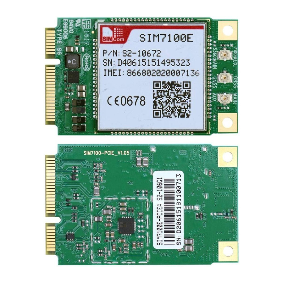
Smart Machine Smart Decision 6 Product label Top and Bottom view of the SIM7100A/C/E/CE/JC/JE-PCIE Main: Main antenna RF connector ; Div: Div antenna RF connector; Div antenna Main antenna Figure 29: the Lable of SIM7100-PCIE Figure 30: the Lable of SIM7100-PCIEA SIM7100-PCIE_Hardware_Design_V1.05 2017-02-24... -
Page 42: Appendix
Smart Machine Smart Decision Appendix I. Coding Schemes and Maximum Net Data Rates over Air Interface Table 30: Coding Schemes and Maximum Net Data Rates over Air Interface Multislot definition(GPRS/EDGE) Slot class DL slot number UL slot number Active slot number GPRS coding scheme Max data rata(4 slots)... - Page 43 Smart Machine Smart Decision Category 6 3.6Mbps 16QAM,QPSK Category 7 7.2Mbps 16QAM,QPSK Category 8 7.2Mbps 16QAM,QPSK Category 9 10.2Mbps 16QAM,QPSK Category 10 14.4Mbps 16QAM,QPSK Category 11 0.9Mbps QPSK Category 12 1.8Mbps QPSK Category 13 17.6Mbps 64QAM Category 14 21.1Mbps 64QAM Category 15 23.4Mbps 16QAM...
-
Page 44: Related Documents
Smart Machine Smart Decision II. Related Documents Table 31: Related Documents Title Description SIM7100_ATC_V0.xx SIM7100_ATC_V0.xx ITU-T Draft new Serial asynchronous automatic dialing and control recommendationV.25ter Digital cellular telecommunications (Phase 2+); AT command GSM 07.07 set for GSM Mobile Equipment (ME) GSM 07.10 Support GSM 07.10 multiplexing protocol Digital cellular telecommunications (Phase 2+);... - Page 45 Smart Machine Smart Decision 27 January 2003 on the restriction of the use of certain hazardous substances in electrical and electronic equipment (RoHS) [21] Module Module secondary SMT Guidelines secondary-SMT-UGD-V1.xx [22] SIM7100_UART_Application This document describes how to use UART interface of _Note_V0.xx SIMCom SIM7100 modules.
-
Page 46: Terms And Abbreviations
Smart Machine Smart Decision III. Terms and Abbreviations Table 32: Terms and Abbreviations Abbreviation Description Analog-to-Digital Converter Antenna Reference Point Bit Error Rate Base Transceiver Station Coding Scheme Circuit Switched Data Clear to Send Digital-to-Analog Converter Discontinuous Reception Digital Signal Processor Data Terminal Equipment (typically computer, terminal, printer) Data Terminal Ready Discontinuous Transmission... - Page 47 Smart Machine Smart Decision Terminal Equipment, also referred to as DTE Transmit Direction UART Universal Asynchronous Receiver & Transmitter VSWR Voltage Standing Wave Ratio SIM phonebook Not connect EDGE Enhanced data rates for GSM evolution HSDPA High Speed Downlink Packet Access HSUPA High Speed Uplink Packet Access Zero intermediate frequency...
-
Page 48: Safety Caution
Smart Machine Smart Decision IV. Safety Caution Table 33: Safety caution Marks Requirements When in a hospital or other health care facility, observe the restrictions about the use of mobiles. Switch the cellular terminal or mobile off, medical equipment may be sensitive to not operate normally for RF energy interference. - Page 49 Smart Machine Smart Decision Contact us: Shanghai SIMCom Wireless Solutions Co.,Ltd. Add: SIM Technology Building, No.633, Jinzhong Road, Changning District, Shanghai P.R. China 200335 Tel: +86 21 3252 3300 Fax: +86 21 3252 3020 URL: www.simcomm2m.com SIM7100-PCIE_Hardware_Design_V1.05 2017-02-24...
Need help?
Do you have a question about the SIMCom SIM7100-PCIE and is the answer not in the manual?
Questions and answers