Multitech MultiModem MTCBA-G-F1 User Manual
Multimodem gprs external wireless modem
Hide thumbs
Also See for MultiModem MTCBA-G-F1:
- User manual (29 pages) ,
- Quick start manual (17 pages) ,
- Reference manual (203 pages)
Table of Contents
Advertisement
Quick Links
Download this manual
See also:
Reference Manual
Advertisement
Table of Contents

Subscribe to Our Youtube Channel
Related Manuals for Multitech MultiModem MTCBA-G-F1


Summary of Contents for Multitech MultiModem MTCBA-G-F1
- Page 1 ® MultiModem GPRS External Wireless Modem MTCBA-G-F1 MTCBA-G-F2 User Guide...
- Page 2 User Guide for MultiModem® GPRS External Wireless Modem Models MTCBA-G-F1 & MTCBA-G-F2 P/N S000304J, Revision J Copyright © 2005 by Multi-Tech Systems, Inc. All rights reserved. This publication may not be reproduced, in whole or in part, without prior expressed written permission from Multi-Tech Systems, Inc.
-
Page 3: Table Of Contents
Chapter 1 – Description & Specification Contents Chapter 1: Product Description and Specifications................4 Product Description ........................... 4 Package Contents ..........................4 Interfaces ..............................4 Parts to be Supplied by Wireless Service Provider................4 Parts to be Supplied by End User ......................4 Antenna/RF Specifications ........................ -
Page 4: Chapter 1: Product Description And Specifications
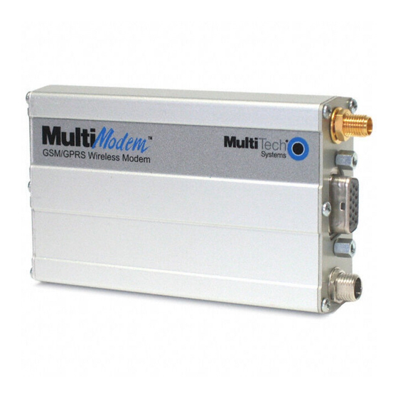
Chapter 1 – Description & Specification Chapter 1: Product Description and Specifications Product Description The Multi-Tech MultiModem® GPRS is an external data/fax/voice wireless modem. It also supports mobile originated short message service (SMS) and mobile-terminated SMS. It offers standards-based multi-band GSM/GPRS Class 10 performance. -
Page 5: Antenna/Rf Specifications
Chapter 1 – Description & Specification Antenna/RF Specifications If the antenna shipped with the bundled version does not meet your application requirements (for size, shape,mounting style, etc.), you may supply an antenna yourself. The antenna used must be of the correct frequency and must be a style appropriate to the application. -
Page 6: Features
Chapter 1 – Description & Specification Features • GPRS Class 10 operation • Dual-band 850/1900 or 900/1800 GSM/GPRS • GSM Class 1 and Class 2 Group 3 FAX • Desktop or panel mounting • Short Message Services including text and PDU, point-to-point, cell broadcast •... -
Page 7: Application Overview
Chapter 1 – Description & Specification Application Overview Application Types With circuit switched data rates up to 14.4K bps, the MultiModem GRPS Wireless Modem is targeted at applications that periodically need to send or receive data over a wireless network. It is an ideal solution for: Appliances ATM Terminals... -
Page 8: Benefits/Features In Applications
Chapter 1 – Description & Specification Benefits/Features in Applications Short Development Time. The MultiModem GRPS Wireless Modem can make your existing and next generation device, machine, or system, communication-ready without requiring any hardware changes to its design. It actually provides faster time-to-market because it relieves the burden and expense of obtaining network and RF approvals. -
Page 9: Functions - Gsm Modes
Chapter 1 – Description & Specification Functions – GSM Modes MODE DESCRIPTION Standard Dual Band Extended GSM 900 MHz Class 4 (2W) and GSM 1800/1900 MHz Class 1 (1W) Interface Serial interface RS232. V.24/V.28 Autobauding function. AT command set based on V.25ter and GSM 07.05 & 07.07 Mobile Originated (MO) and Mobile Terminated (MT) SMS Mode Text &... -
Page 10: Specifications
Chapter 1 – Description & Specification Specifications General Specifications Power Requirements 5 V to 32VDC; 400mA Average @5V, 1A Peak @ 5V Mechanical Dimensions & Weight 4.3" w x 2.4" h x 0.94" d; 4.1 oz. (11 cm x 6.1 cm x 2.4 cm; 115 g) Connectors &... -
Page 11: Led Indicators
Chapter 1 – Description & Specification LED Indicators TD. Transmit Data. Lit when modem is transmitting data. RD. Receive Data. Lit when modem is receiving data. CD. Carrier Detect. Lit when data connection has been established. LS. Line Status. Continuous “on” state indicates that the wireless modem is not registered on the network. -
Page 12: Chapter 2: Installation
Chapter 2 – Installation Chapter 2: Installation Mechanical Mounting To mount the Wireless MultiModem, do the following: 1. Obtain mounting screws (two are needed) that are appropriate for the surface on which you will mount the modem. The mounting screw on the connector end of the unit must have a screw- head no thicker than 2 mm. - Page 13 Chapter 2 – Installation 3. Slide the mounting bridles into the corresponding slots on the backside of the modem chassis. 4. Attach the modem with two screws to the mounting surface at the desired location on the equipment. Multi-Tech Systems, Inc. MultiModem® GPRS User Guide...
-
Page 14: Electrical Installation & Configuration
Chapter 2 – Installation Electrical Installation & Configuration The wireless MultiModem requires the power supply connection to begin operation. It also requires a SIM card (Subscriber Identity Module) to operate on a GSM network. To install the modem, do the following: 1. -
Page 15: Antenna Connector
Chapter 2 – Installation 4. Connect a suitable antenna to the SMA connector (see specifications on page 5). Antenna Connector (SMA type) 5. Connect both sides of the serial and control cable (15-pin Sub D connector on the modem side). Serial &... -
Page 16: Power Cable
Chapter 2 – Installation 6. Plug the power supply cable into the modem. Fused DC Power Cable In-Line Fuse For standard transformer power supply • Connect the AC cord receptacle into the transformer block. • Connect the AC cord plug into the mains power outlet. For optional direct-DC powering •... -
Page 17: Mobile Phonetools
Chapter 2 – Installation Mobile Phonetools For initial configuration of your wireless device, Multi-Tech offers a Windows based mobile Phone Tools application. To load mobile Phone Tools, click on the mobile Phone Tools icon on your MultiModem CD and follow the on-screen prompts. Direct Modem Installation To install the Wireless MultiModem directly into the computer's Windows OS so it is independent of the mobile Phonetools program, use the "Add Modem"... -
Page 18: Verifying Network Registration
Chapter 2 – Installation Verifying Network Registration In this procedure, you will verify that the Wireless MultiModem has been registered on the wireless network. To do so, you will use the common communications program Hyperterminal. 1. Using the Hyperterminal program at the computer to which the Wireless MultiModem is connected, type the AT command AT+CREG?. -
Page 19: Testing The Configuration
Chapter 2 – Installation Testing the Configuration Description Response Returned Comments Commands AT+CPIN PIN Code accepted =1234 Enter PIN Code +CME ERROR : 16 Incorrect PIN Code +CME ERROR : 3 PIN already entered (with +CMEE : 1 mode) AT + CREG ? CREG = <mode>, 1 modem synchronized on the network CREG = <mode>, 2 synchronization lost, re-synchronization... -
Page 20: Chapter 3: Troubleshooting
Chapter 3 – Troubleshooting Chapter 3: Troubleshooting Troubleshooting Examples Situation A: The modem does not answer through the serial link If the Wireless MultiModem does not answer through the serial link upon an attempted transmission of data or voice signals, see the table below for possible causes and solutions. Solutions for ‘no connection through serial link’... -
Page 21: Situation B: The Modem Always Returns «Error» When Trying To Issue A Communication
Chapter 3 – Troubleshooting Situation B: The modem always returns «Error» when trying to issue a communication If the Wireless MultiModem returns a message of error upon an attempted transmission of data or voice signals, see the table below for possible causes and solutions. Solutions for “error”... -
Page 22: Situation C: The Modem Always Returns «No Carrier» When Trying To Issue A Communication
Chapter 3 – Troubleshooting Situation C: The modem always returns «No carrier» when trying to issue a communication Solutions for “no carrier” message If the modem returns … Then ask … Action no carrier Is the selected Type AT+CEER to view the extended (esp. -
Page 23: Chapter 4: Safety
Chapter 4 – Safety Chapter 4: Safety Safety General Safety The modem is designed for and intended to be used in fixed and mobile applications. “Fixed” means that the device is physically secured at one location and is not able to be easily moved to another location. “Mobile” means that the device is designed to be used in other than fixed locations and generally in such a way that a separation distance of at least 20 cm (8 inches) is... -
Page 24: Vehicle Safety
Chapter 4 – Safety Vehicle Safety • Do not use your Wireless MultiModem while driving, unless equipped with a correctly installed vehicle kit allowing ‘Hands-Free’ Operation. • Respect national regulations on the use of cellular telephones in vehicles. Road safety always comes first. -
Page 25: Chapter 5: Warranty And Repairs
Please direct your questions regarding technical matters, product configuration, verification that the product is defective, etc., to our Technical Support department at (800) 972-2439 or email support@multitech.com. Please direct your questions regarding repair expediting, receiving, shipping, billing, etc., to our Repair Accounting department at (800) 328-9717 or (763) 717-5631, or email mtsrepair@multitech.com. -
Page 26: Repair Procedures For International Customers
Please direct your questions regarding technical matters, product configuration, verification that the product is defective, etc., to our Technical Support department nearest you or email support@multitech.com. When calling the U.S., please direct your questions regarding repair expediting, receiving, shipping, billing, etc., to our Repair Accounting department at +(763) 717-5631 in the U.S.A., or email mtsrepair@multitech.com. -
Page 27: Chapter 6: Reference Information
F-06921 Sophia Antipolis Cedex, France e-mail: secretariat@etsi.fr Service: The AT commands manual is available on the Multi-Tech web site: http://www.multitech.com Disclaimer Wireless MultiModem specifications and manuals are subject to change without notice. MTS assumes no liability for damage incurred directly or indirectly from errors, omissions or discrepancies between the Wireless MultiModem and its manual. -
Page 28: Data Cable Diagram, Wireless Multimodem With Voice
Chapter 6: Reference Information Data Cable Diagram, Wireless MultiModem with Voice Multi-Tech Systems, Inc. MultiModem® GPRS User Guide... -
Page 29: Appendix A - Waste Electrical And Electronic Equipment (Weee) Statement
Appendix A – WEEE Statement Appendix A - Waste Electrical and Electronic Equipment (WEEE) Statement July, 2005 The WEEE directive places an obligation on EU-based manufacturers, distributors, retailers and importers to take-back electronics products at the end of their useful life. A sister Directive, ROHS (Restriction of Hazardous Substances) complements the WEEE Directive by banning the presence of specific hazardous substances in the products at the design phase.
Need help?
Do you have a question about the MultiModem MTCBA-G-F1 and is the answer not in the manual?
Questions and answers