Advertisement
Quick Links
REVISION HISTORY
Issue
Number
Draft 1
First Release
Update #1
Gemini Two Tube Clock
Update #1 (21
st
May 2019)
www.nixology.uk
Assembly Instructions
Gemini Two tube clock
nixology.uk
Date
Reason for Issue
24/04/2019 New document
06/05/2019
21/05/2019 Added initial setup and updating info
1
Advertisement

Related Manuals for Nixie Clock Gemini Two


Summary of Contents for Nixie Clock Gemini Two
- Page 1 Assembly Instructions Gemini Two tube clock nixology.uk REVISION HISTORY Issue Date Reason for Issue Number Draft 1 24/04/2019 New document First Release 06/05/2019 Update #1 21/05/2019 Added initial setup and updating info Gemini Two Tube Clock Update #1 (21 May 2019)
- Page 2 Gemini Two Tube Clock – Features • Hours, Minutes and Seconds display • Date Display • Temperature and Pressure display • Drives a wide range of tubes • Reliant on access to an NTP Time source for operation • WiFi connection configured via a captive portal on the clocks own Access Point •...
- Page 3 Tube cells for the larger tube types incorporate connections for additional APA106 LED’s *Depending on the chosen tube type it may be necessary to change R3 and R4 from the 10k supplied to match your tubes. Gemini Two Tube Clock Update #1 (21 May 2019) www.nixology.uk...
-
Page 4: Electric Shock
This is not a finished product, and the person assembling the kit is responsible for ensuring that the finished product complies with any applicable local regulations governing electrical equipment. Gemini Two Tube Clock Update #1 (21 May 2019) www.nixology.uk... - Page 5 R1 – R4 and the 8 pin DIL socket on the top side. DO NOT insert the WeMos, HV Power supply or other IC’s before you have successfully measured 5V from the 5V test point. Gemini Two Tube Clock Update #1 (21 May 2019) www.nixology.uk...
- Page 6 2mA. From Ohms Law (i=v/r or r=v/i), r=(170-140)/0.002 = 15K Similarly, for a ZM1175 from Mullard, it has a maintaining voltage of 145V and requires 2.5mA so r=(170-145)/0.0025 = 10K Gemini Two Tube Clock Update #1 (21 May 2019) www.nixology.uk...
- Page 7 Gemini Two Tube Clock Update #1 (21 May 2019) www.nixology.uk...
- Page 8 ‘notch’ in the socket with the symbol on the PCB. Next Add the two 2x6 male headers for the tube connections. Next Add the 8 pin DIL socket for the Opto Couplers. Gemini Two Tube Clock Update #1 (21 May 2019)
- Page 9 4 pins that came with the power supply to the power supply itself. Next push 4 x socket pins onto the power supply pins and inset the completed assembly into the PCB and solder the socket pins to the main board. Gemini Two Tube Clock Update #1 (21 May 2019)
- Page 10 Remove the power supply and trim the short ends of the socket pins on the other side of the board. Mounting pins cut off after soldering (NCH8200HV mounted on bottom of board) NCH8200HV when mounted on the top of the board Gemini Two Tube Clock Update #1 (21 May 2019) www.nixology.uk...
- Page 11 NCH8200HV mounted on the bottom of the board Remove the NCH8200HV from the clock Gemini Two Tube Clock Update #1 (21 May 2019) www.nixology.uk...
- Page 12 PCB ‘long’ end first, leaving the ‘short’ ends for soldering to the WeMos (for location only DO NOT SOLDER). Put the Wemos on to the two rows of pins and solder the pins to the Wemos ONLY. Gemini Two Tube Clock Update #1 (21 May 2019)
- Page 13 Take care to orient the WeMos correctly so that the pins get soldered to the correct side! Gemini Two Tube Clock Update #1 (21 May 2019) www.nixology.uk...
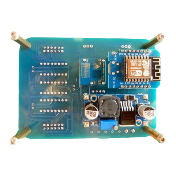
- Page 14 The purpose of plugging the WeMos in at this stage is to help get the socket headers straight. Turn the board over and solder the sockets in to place. Your board should now look like this: Gemini Two Tube Clock Update #1 (21 May 2019) www.nixology.uk...
- Page 15 ‘Alternative Space Saving’ method Follow the same procedure as used for the NCH8200HV power supply. Start by soldering 4 x pins to the underside of the Buck converter (Not the component side). Gemini Two Tube Clock Update #1 (21 May 2019) www.nixology.uk...
- Page 16 Mount the Buck Converter on the underside of the PCB taking care to mount it the right way around the solder in to place from the top side of the PCB. Gemini Two Tube Clock Update #1 (21 May 2019)
- Page 17 IC socket pins. REMEMBER, THIS MUST BE DONE AFTER soldering R1, R2, R3, R4 and the 8 pin DIL socket in to place and trimming their leads. Gemini Two Tube Clock Update #1 (21 May 2019) www.nixology.uk...
- Page 18 1 x BMP280 sensor module – this can be mounted directly or via a length of cable if remote mounting is preferred. If it is not properly connected then the temperature and pressure will not be displayed. Gemini Two Tube Clock Update #1 (21 May 2019)
- Page 19 Plug in the following on the bottom of the PCB 1 x WeMos D1 Mini, taking care to align the pins correctly and orient the WeMos so that the ‘Antenna’ end is closest to the outside edge of the PCB. Gemini Two Tube Clock Update #1 (21 May 2019)
- Page 20 The software is using a standard Library for managing the WiFi connection. When it fails to connect, it will set itself up as an Access Point with a Captive Portal. Gemini Two Tube Clock Update #1 (21 May 2019) www.nixology.uk...
- Page 21 5 minutes during daytime and 1 minute during night-time after which it will go off until re-activated. The clock has been tested with the following types commonly available of PIR: Gemini Two Tube Clock Update #1 (21 May 2019)
- Page 22 Gemini Two Tube Clock Update #1 (21 May 2019) www.nixology.uk...
- Page 23 Once running you should see the clock status giving details of what is being sent to the tubes etc. This can be done either with the WeMos mounted on the clock PCB or with the WeMos removed and in complete isolation. Gemini Two Tube Clock Update #1 (21 May 2019) www.nixology.uk...
- Page 24 The clock is active between 06:00 and 21:00. Connection of a PIR overrides these times. The PIR activation period is set to 1 minute between 21:00 and 06:00, it is set to 5 minutes between 06:00 and 21:00. Gemini Two Tube Clock Update #1 (21 May 2019)
- Page 25 WeMos is connected to your LAN and is at IP 192.168.100.125, the password for OTA uploads is ‘Z566’): python.exe espota.py -i 192.168.100.125 -p 8266 –auth=Z566 -f C:\bin\GemeniOTA-PIR-Async-BMPckeck.ino.bin Here is a link to an instructable on OTA programming: https://www.instructables.com/id/IoT-Over-the-Air-Update-OTA-ESP8266/ Gemini Two Tube Clock Update #1 (21 May 2019) www.nixology.uk...
Need help?
Do you have a question about the Gemini Two and is the answer not in the manual?
Questions and answers