Table of Contents
Advertisement
Quick Links
USER MANUAL
NI REM-11180
Bus Coupler for Remote I/O
This document describes the features of the NI REM-11180 and contains information about
mounting and operating the device.
EtherCAT
In
EtherCAT
Out
Service
Port
Reset
Button
U
(24 V)
L
Contents
REM-11180 Features................................................................................................................ 2
Ports and Connectors........................................................................................................ 3
Reset Button...................................................................................................................... 4
LEDs................................................................................................................................. 5
Dimensions................................................................................................................................8
Configuring the Rotary Encoding Switch................................................................................. 8
Restoring Default Settings........................................................................................................ 9
Reading Error Codes from REM-11180 IOVs..........................................................................9
Diagnostics..............................................................................................................................10
Diagnosis History Object................................................................................................ 10
Diagnostic Registers........................................................................................................11
User Error Codes.............................................................................................................12
Bus Diagnostic Error Codes............................................................................................19
RJ45
RJ45
Isolation
Power
Supply
GND
Microcontroller
Local
Bus
U
bus
Advertisement
Table of Contents

Related Manuals for National Instruments REM-11180


Summary of Contents for National Instruments REM-11180
-
Page 1: Table Of Contents
USER MANUAL NI REM-11180 Bus Coupler for Remote I/O This document describes the features of the NI REM-11180 and contains information about mounting and operating the device. EtherCAT RJ45 EtherCAT RJ45 Isolation Service Port Local Microcontroller Reset Button (24 V) -
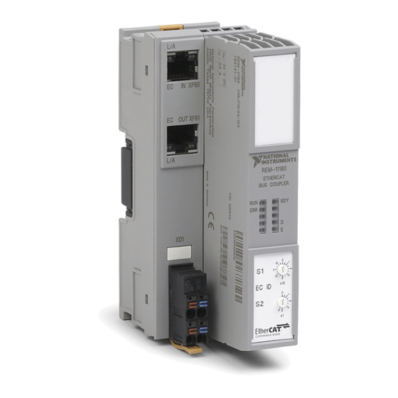
Page 2: Rem-11180 Features
The REM-11180 provides the following features. Figure 1. Structure of the REM-11180 1. Bus connector 5. Supply voltage connector 2. REM-11180 6. Rotary encoding switch 3. Ethernet connectors 7. LED indicators 4. Module function label 2 | ni.com | REM-11180 User Manual... -
Page 3: Ports And Connectors
1. Ethernet In 2. Ethernet Out Table 1. RJ-45 Ethernet Port Pinout Fast Ethernet Signal Pinout TXD+ TXD- RXD+ Reserved Reserved RXD- Reserved Reserved Figure 3. Power Connector 24 VDC 24 VDC REM-11180 User Manual | © National Instruments | 3... -
Page 4: Reset Button
You do not need to connect to this port for normal operation. Reset Button Pressing the reset button during normal operation restarts the bus coupler. Figure 5. REM-11180 Reset Button 1. Label 2. Reset button 4 | ni.com | REM-11180 User Manual... -
Page 5: Leds
Bus coupler in Pre-Operational state (2.5 Hz) 200 ms on, 1000 ms off; bus coupler in Safe- Single pulse Operational state Green Solid Bus coupler in Operational state Flashing (10 Bus coupler in Bootstrap state REM-11180 User Manual | © National Instruments | 5... - Page 6 Firmware/bus coupler is booting Yellow Flashing Firmware update is being performed. Yellow/Red Solid Firmware update has failed. Rotary encoding switches are set to an invalid/ Solid reserved position Unlit Device is not ready to operate. 6 | ni.com | REM-11180 User Manual...
- Page 7 Serious device error at a local bus device (local bus device can no longer be reached) Yellow Solid I/O warning at a local bus device Solid I/O error at a local bus device Figure 8. Ethernet LEDs REM-11180 User Manual | © National Instruments | 7...
-
Page 8: Dimensions
Flashing EC OUT. — Connection not present at EC IN/EC OUT. Dimensions The following figures show the front and side dimensions of the REM-11180. For detailed dimensional drawings and 3D models, visit ni.com/dimensions and search for the module number. Figure 9. REM-11180 Dimensions 45.0 mm... -
Page 9: Restoring Default Settings
Release the button when the RDY LED flashes red and green. Reading Error Codes from REM-11180 IOVs When you add the REM-11180 to the RT Target in the LabVIEW project, the following IOVs are available: Table 6. LabVIEW Project IOVs for Remote I/O Systems... -
Page 10: Diagnostics
Newest acknowledged message New message available Behavior setting for the object Note Refer to Table 27: Entries of 0x10F3 Diagnosis History Object in the ETG. 1020 EtherCAT Protocol Enhancements document for Newest Acknowledged Message definitions. 10 | ni.com | REM-11180 User Manual... -
Page 11: Diagnostic Registers
The controller is in the STOP state or no application program has been loaded. F_BASP_BIT SYS_FAIL Output data is blocked (substitute value behavior). F_FORCE_BIT Force mode Force mode (start-up tool) is active. 11 to 15 — — Reserved REM-11180 User Manual | © National Instruments | 11... -
Page 12: User Error Codes
Code of the Call of an unknown service code. Check the call. unknown service An exclusive service was to be Wait for the exclusive — executed without the appropriate rights to be enabled. rights. 12 | ni.com | REM-11180 User Manual... -
Page 13: Reserved
Incorrect The number of variables has been 093B Check the call. Variable_Count calculated incorrectly. Restart the device. A hardware or firmware error 0A01 — Contact NI if the occurred. problem persists. REM-11180 User Manual | © National Instruments | 13... - Page 14 1000 Param Ready Fail (Communication abort in Ready parameter) 2000 Run Fail (Process data traffic with subsystem) 4000 Force Fail (Application timeout for all devices) 8000 Force Mode Fail (Communication abort in Force_Mode) 14 | ni.com | REM-11180 User Manual...
- Page 15 (if specified) Number of Maximum number of devices Reduce the bus 0A1C connected devices exceeded. configuration. Connect the device and 0A2F — Number of devices is zero. check the connection. REM-11180 User Manual | © National Instruments | 15...
- Page 16 0A77 Device number Error at the interface. module and bus base module. Invalid Dev_Type specified 0A7 A — Check the parameters. during loading. Invalid Dev_ID specified during 0A7B — Check the parameters. loading. 16 | ni.com | REM-11180 User Manual...
- Page 17 Input_Delay. Device was selected for Select a different value synchronization, but does not 0A93 Device number for Output_Delay or a support the specified value for different device. Output_Delay. REM-11180 User Manual | © National Instruments | 17...
- Page 18 Restart the device. Access not supported. (E.g., write 0B06 — Contact NI if the protection) problem persists. 0B07 — Object does not exist. — A hardware or firmware error 0B0C — — occurred. 18 | ni.com | REM-11180 User Manual...
-
Page 19: Bus Diagnostic Error Codes
An additional device Device Adapt the configuration 0C02 was added at the end of the physical number frame if the modification bus structure after the configuration was done on purpose. frame was connected. REM-11180 User Manual | © National Instruments | 19... - Page 20 Check the configuration. Device The module ID does not correspond Adapt the configuration 0C15 number to the configured value. frame if the modification was done on purpose. 20 | ni.com | REM-11180 User Manual...
- Page 21 Cold junction invalid Cold junction Check the cold junction. 5160 Supply voltage faulty Supply fail Check the I/O supply. Parameter set not Check the parameterization of 6300 Parameter set faulty the specified device. REM-11180 User Manual | © National Instruments | 21...
- Page 22 Check the input signal. Input error of Encoder input Remove the short circuit. 8600 incremental encoder signal error Connect the sensor. 8910 Overrange Overrange Adapt the range. Check the wiring. 8920 Underrange Underrange 22 | ni.com | REM-11180 User Manual...
- Page 23 Restart the device. Contact NI 0F02 — Hardware or firmware error if the problem persists. 0F03 0F04 Inconsistent parameters Check the parameters. 0F05 PDI object index Invalid parameters Check the parameters. REM-11180 User Manual | © National Instruments | 23...
- Page 24 Check the call. length Invalid number 0F24 Invalid number of parameters. Check the call. of parameters 0F31 — Restart the device. Contact NI 0F32 — Internal error if the problem persists.. 0F33 — 24 | ni.com | REM-11180 User Manual...
- Page 25 Communication object cannot be mapped to the process data. Process data length exceeded Hardware error Application failed Invalid segment number, e.g., upload without initiation with subindex 00A0 ==FFhex. 00A1 Resource not available; No more resources (memory) available for download. REM-11180 User Manual | © National Instruments | 25...
- Page 26 78759-3504. NI also has offices located around the world. For telephone support in the United States, create your service request at ni.com/support or dial 1 866 ASK MYNI (275 6964). For telephone support outside the United States, visit the Worldwide Offices section of ni.com/ 26 | ni.com | REM-11180 User Manual...
- Page 27 REM-11180 User Manual | © National Instruments | 27...
- Page 28 NI trademarks. Other product and company names mentioned herein are trademarks or trade names of their respective companies. For patents covering NI products/technology, refer to the appropriate location: Help»Patents in your software, the file on your media, or the National Instruments Patent Notice at . You can find patents.txt ni.com/patents...
Need help?
Do you have a question about the REM-11180 and is the answer not in the manual?
Questions and answers