Advertisement
Table of Contents
- 1 Components
- 2 Safety Information
- 3 Connections
- 4 Flushing
- 5 After Installation
- 6 Step-By-Step Instructions
- 7 This Appliance Must be Earthed
- 8 Adjustable Height Head
- 9 Ceiling Mounted
- 10 Ceiling Flush Mounted
- 11 Wall Mounted
- 12 Control
- 13 Fixed Head User Guide
- 14 Cleaning
- 15 Typical Installations
- Download this manual
Axis
Digital
Concealed standard and pumped
The Waste Electrical and Electronic Equipment (Producer Responsibility) Regulation 2004
This product is outside the scope of the European Waste Electrical and Electronic Equipment Directive as interpreted within the UK.
In the UK this product can therefore be disposed of through commercial non-WEEE waste facilities.
The original manufacturer does not accept any liability under the WEEE directive.
Axis Digital concealed installation instuctions
®
page 1
Advertisement
Table of Contents

Related Manuals for Aqualisa Axis Digital AX8110


Summary of Contents for Aqualisa Axis Digital AX8110
- Page 1 Axis ® Digital Concealed standard and pumped The Waste Electrical and Electronic Equipment (Producer Responsibility) Regulation 2004 This product is outside the scope of the European Waste Electrical and Electronic Equipment Directive as interpreted within the UK. In the UK this product can therefore be disposed of through commercial non-WEEE waste facilities. The original manufacturer does not accept any liability under the WEEE directive.
- Page 2 Shower systems Axis Digital concealed standard With Axis adjustable With Axis wall With Axis ceiling height head mounted fixed head mounted fixed head AX8130 AX8110 AX8120 Axis Digital concealed pumped With Axis adjustable With Axis wall With Axis ceiling height head mounted fixed head mounted fixed head AX8135...
- Page 3 Components Axis Digital concealed standard With Axis adjustable With Axis wall With Axis ceiling height head mounted fixed head mounted fixed head AX8130 AX8110 AX8120 Axis Digital concealed pumped With Axis adjustable With Axis wall With Axis ceiling mounted fixed head height head mounted fixed head AX8135...
- Page 4 Important information Safety information This product must be installed by a competent person in accordance with all relevant Water and Wiring Supply Regulations. Electrical supply and bonding of the bathroom must comply with the current IEE regulations, and your attention is drawn to the requirements concerning protective earth bonding.
- Page 5 Step-by-step instructions In addition to the guide below it is essential that the written instructions opposite are read and understood and that you have all the necessary components (shown above) before commencing installation. Failure to install the product in accordance with these instructions may adversely affect the warranty terms and conditions.
- Page 6 Choose the position for your Digital processor as close to the shower control as possible. The processor may be sited in the roof space above the proposed shower site, in the airing cupboard or behind a screwed bath panel if more convenient.
- Page 7 Run a pipe from the mixed water outlet on the Digital processor through the wall or ceiling to the proposed siting for the shower hose outlet, fixed head or diverter depending on the system purchased. Place the mounting bracket on the wall in the desired location for the control and mark the position of the three fixing holes and the data cable entry point.
- Page 8 Connect the power lead to a 3 amp fused switched spur. Ensure that this is in an accessible location and not in the bathroom. The fused spur must provide a contact separation of at least 3mm from the supply in all poles (Live and Neutral). THIS APPLIANCE MUST BE EARTHED The data cable and power lead can be routed in the grooves provided under the processor.
- Page 9 Adjustable height head The adjustable height head is supplied with masonry fixings intended for use with a wall of solid construction only. If the unit is to be installed on a wall of different construction then please use alternative fixings as required. Prepare pipe work from the shower valve/processor to the required position for the hose...
- Page 10 Mount the template to the wall in the required position ensuring vertical alignment using a spirit level to facilitate if necessary. Carefully mark the two fixing holes. Check the intended position for the rail assembly before removing the template, then drill and prepare suitable wall fixings for the two mounting screws.
- Page 11 Attach the shower hose only to the outlet and flush through the system for 15 seconds to clear any debris before fitting the shower head. Thread the shower hose through the hose restraint before attaching the head and fitting it to the handset holder.
- Page 12 Set the fixing bracket into position and mark the fixing points. Remove the bracket and drill and prepare suitable fixings. Refit the fixing bracket and secure it through the ceiling and into the noggin using the screws provided if suitable. Refit the cover plate onto the fixed head arm and feed it through the fixing bracket...
- Page 13 Ceiling flush mounted The ceiling flush mounted fixed head is supplied with screws for fixing the product to a noggin. A NOGGIN MUST BE USED AS PART OF THIS INSTALLATION Before starting installation of the flush mounted fixed head it is imperative that the installation notes below are read and understood and that checks are made to ensure that there is sufficient space behind the ceiling as required.
- Page 14 Remove the cover plate and fixing bracket carefully from the fixed head arm. Set the fixing bracket into position (above the noggin) and mark the fixing points. Remove the bracket and drill and prepare suitable fixings. Refit the fixing bracket and secure it to the noggin using the screws provided if suitable.
- Page 15 Connect the pipe work from the valve to the pipe work for the fixed head. Check that the shower head is still in the correct position before fully tightening the nut on the ceiling mounting bracket using a 32mm spanner. Check the installation for leaks then fit the badge to the front of the spray plate.
- Page 16 Insert the red 3/8” BSP plug into the front of the spigot and tighten. Turn on the shower valve to pressurise the system and thoroughly check the outlet assembly for any leaks. Turn off the valve and leave the plug in place to prevent ingress of debris during the making good process.
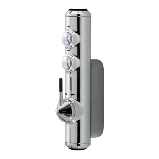
- Page 17 User Guide Control 1. Turn the temperature dial to the required setting. 2. Press the ‘start’ button on the control. 3. The red and blue LED display will flash until the selected temperature has been reached. 4. When the LED display is constant, step into your shower and enjoy! 5.
- Page 18 Typical installations Typical gravity system installation Typical Thermal storage unit system installation NB: THE BASE OF THE PROCESSOR Supply MUST BE SITED NO HIGHER THAN THE BASE LEVEL OF THE CISTERN Vent and draw-off pipe to hot water Digital shower control Cold feed to cylinder...
- Page 19 Brochure Hotline: 0800 652 3669 Website: www.aqualisa.co.uk Email: enquiries@aqualisa.co.uk Please note that calls may be recorded for training and quality purposes The company reserves the right to alter, change or modify the product specifications without prior warning ® Registered Trademark Aqualisa Products Limited...
Need help?
Do you have a question about the Axis Digital AX8110 and is the answer not in the manual?
Questions and answers