Table of Contents
Advertisement
Quick Links
Advertisement
Table of Contents

Related Manuals for Megger FRAX Series


Summary of Contents for Megger FRAX Series
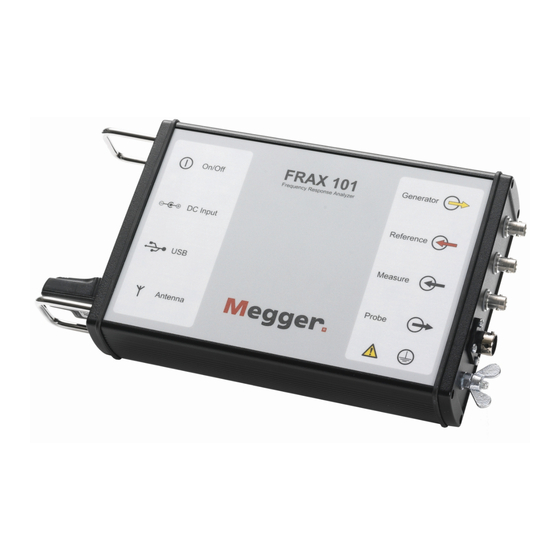
- Page 1 FRAX-series Sweep frequency analyser User guide...
- Page 2 2008-2023, Megger Sweden AB. All rights reserved. The contents of this manual are the property of Megger Sweden AB. no part of this work may be reproduced or transmitted in any form or by any means, except as permitted in written license agreement with Megger Sweden AB. Megger Sweden AB has made every reasonable attempt to ensure the completeness and accuracy of this document.
-
Page 3: Table Of Contents
5.10. File description ........................49 5.11. Test description ........................49 5.12. Measurement settings ......................50 5.13. Views ..........................50 5.14. Legend action button description ..................51 5.15. Correlation analysis ......................51 5.16. Exit (Alt+F4) ......................... 52 5.17. Connect ..........................52 www.megger.com FRAX-series... - Page 4 7. Appendix ........................... 55 7.1. Appendix A. Calibration instruction ..................55 7.2. Appendix B Adjusting output voltage ..................58 7.3. Appendix C. Test name settings ....................59 7.4. Appendix D. Cables and clamps ..................... 62 8. Index ............................65 FRAX-series www.megger.com...
-
Page 5: Introduction
1.2. Company website Occasionally an information bulletin may be issued via the Megger website. This may concern new accesso- ries, new usage instructions or a software update. Please occasionally check on the Megger web site for anything applicable to your Megger instruments. -
Page 6: Calibration
E-mail: support-sweden@megger.com Service, repair & calibration Megger has a wide network of authorized service centers. Please consult your local representative or the webpage for an up-to date listing. Service, repair and calibration is also available at the service center at the manufacturing site in Sweden. -
Page 7: Contact Information
Equipment returned to the factory for repair must be shipped prepaid and insured. Contact nearest Megger representative for instructions and a return authorization (RA) number. Please indicate all pertinent information, including problem symptoms. Also specify the serial number and the part number of the unit. -
Page 8: General Safety
WEEE, Waste Electronic Equipment. Please utilize your local WEEE collection facilities in the dispo- sition of this product and otherwise observe all applicable requirements.The unit can also be returned to Megger at any time at no charge for the disposal. 2.2. Warning and caution notices Warning and caution notices are used throughout this user guide where applicable and should be strictly observed and followed. -
Page 9: Placement
▪ Do not exceed the specified input voltage limit on any of the FRAX-series inputs. ▪ Do not apply voltage to the outputs. ▪ Polarity must be red to + and black to −, Timing AUX channels excluded. www.megger.com FRAX-series... -
Page 10: Lightning
Please entrust all servicing to qualified service personnel. If you attempt to service the FRAX-series yourself, the warranty will no longer be valid. In case of return for service, please use either the original transport box or one of equivalent strength. FRAX-series www.megger.com... -
Page 11: Safety Instructions
19. A qualified operator should attend all times while the test equipment is in operation. 20. Observe all safety warnings marked on the equipment. 21. Corrective maintenance must only be performed by qualified personnel who are familiar with the design and operation of the test set and the hazards involved. Maintenance www.megger.com FRAX-series... -
Page 12: Battery Inside
The instrument must be powered off and securely packaged before shipping. ▪ Do not heat or dispose of the battery in a fire. ▪ Do not subject the battery to strong impact, mechanical shock or excessive heat. ▪ Do not short-circuit or reverse the polarity of the battery. FRAX-series www.megger.com... -
Page 13: Instrument Description
WARNING All test objects must be grounded at one end at all times to minimize risks for high voltage interference entering the instrument. www.megger.com FRAX-series... -
Page 14: Front Panel Frax 150
The Bluetooth module used in FRAX 101 is class 1. Also, the Bluetooth USB Adapter that comes as a stand- ard accessory with FRAX is class 1. Using this adapter communicating with FRAX, class 1 communication will be established. FRAX-series www.megger.com... - Page 15 1. Form Windows start menu open “Devices and Printers” and click on “Add a device”. Computer will list all available devices. 2. Find device named “Megger FRAX 101” select it and click “Next”. Computer will connect to device. 3. Click on option “Enter the device’s pairing code”.
-
Page 16: Built-In Battery Pack And Charger
FRAX-101 automatically enters low power consumption mode when waiting for a measurement and be- cause a typical sweep takes approximately 1 minute, the battery lasts for at least 3 hours of measuring or more than 12 hours idle. FRAX-series www.megger.com... -
Page 17: Ground Loop Detector
The rejection of DC offset and harmonics - referred to as the applied voltage - are in theory infinite. By increasing the integration cycles, the rejection gradually improves. www.megger.com FRAX-series... - Page 18 Instrument description The IF bandwidth is commonly used as a parameter defining the bandwidth around the applied signal analyzed. An IF bandwidth of 10 % of active frequency is equivalent to 12 cycles of integration. FRAX-series www.megger.com...
-
Page 19: Quick Start Tutorial
1. Start FRAX software 2. Connect to FRAX by selecting "Connect" from menu File, by clicking "Connect" button on the right hand side of software window or by using F7 key. www.megger.com FRAX-series... -
Page 20: Create A New Test
The file name will be formatted as selected in default filename settings. Click “Save” to save the file. NOTE Information can always be added to the “Nameplate” at any time. This feature makes it possible to add notes during the measurement. FRAX-series www.megger.com... -
Page 21: Test Lead Connection
The test connection polarity is important since reversed polarity will produce different results. The user must establish a polarity convention. In this software it is assumed, and recommended, that H1-H0 imply the red/ yellow connectors (source and reference) is connected to H1 and the black (measure) is connected to H0. www.megger.com FRAX-series... - Page 22 Using an easy repeatable cable setup is crucial to ensure reliable SFRA results. A good idea is to take photos of the connections to ensure repeatability. Bad connection can affect the curve at higher fre- Good connection. quencies. FRAX-series www.megger.com...
- Page 23 Separate the “Source”/”Reference” clip from the “Measure” clip. The clips themselves will give some influence at highest frequencies, if the “Measure” coaxial cable from the FRAX unit is disconnected the graph shows the noise in the measurement system (green). Field test box, FTB-101 www.megger.com FRAX-series...
-
Page 24: Start Measurement
If the hook-up and the equipment is in good working order the sweep should look like in the picture below. The results can be compared with the file “FTB-101.frax” that is shipped with the FRAX software. Available from the installation folder: C:\Program Files(x86)\Megger\FRAX\Measurement examples. More information in Appendix D about connections. 4.6. Start Measurement 1. - Page 25 Allows for viewing data in the FRAX Software. For more details see chapter “FRAX Software”. Export Data If the data needs to be used in other software it is possible to use data files directly or export the data of choice, see Export... in chapter “FRAX Software”, “File menu”. www.megger.com FRAX-series...
-
Page 26: Frax Software
▪ Bluetooth (FRAX-101 only) and USB. Welcome Screen Welcomes to Megger Installer for FRAX. To install FRAX Software press Next which will bring up License Agreement. License Agreement Read the license and check the “I accept the terms in the License Agreement” checkbox. - Page 27 Just drag it into the desired position and release it there. The resizing is limited to ensure that the program is always usable. NOTE During the first six months the program will report all abnormal program terminations to our software department for debugging purposes. www.megger.com FRAX-series...
-
Page 28: File Menu
“Test group” or “Test name” and enter a new name. 3. Select a “Test group” and select which tests that should be included by setting the cross in front of the test name(s) and then press “OK”. For more information see Appendix D. FRAX-series www.megger.com... - Page 29 Then press “OK”. The test names and measurement settings used in the selected file are loaded. Nameplate If “Single Test” or “Multiple Tests” are selected in the “Measurement type” dialog, an almost empty nameplate will appear. The “Test date:” is by default filled in with PC system date. www.megger.com FRAX-series...
- Page 30 The FRAX software comes with a few examples of actual SFRA measurements as well as a reference measurement using the FTB-101. See installation folder, usually C: \Program Files(x86)\Megger\ FRAX\Measurement examples Select File... (Ctrl+F) Find a previously performed measurement in the test database and load it into the graph view.
- Page 31 The Custom Report uses Microsoft Word as report generator. NOTE It will only work if Microsoft Word is installed on the computer. The FRAX150 does not come with MS Word installed and due to the limited hardware, it should not be attempted. www.megger.com FRAX-series...
- Page 32 5. To get the curves on the report they need to be in the FRAX software. Make sure both models and views are loaded. FRAX-series www.megger.com...
- Page 33 Example: If only magnitude graph is displayed, then only magnitude will be exported, if Magnitude and Phase are visible, both Magnitude and Phase will be exported. 2. Column and decimal separators can be changed before exporting the data. Select suitable combination and press OK. www.megger.com FRAX-series...
- Page 34 The print-out will also contain a simple list of the name- plate data. The printout of nameplate data will be in English only. Printout can be obtained in html, pdf, and MS Word formats. Setting logotype is for MS Word reports only. FRAX-series www.megger.com...
- Page 35 It is possible to delete a text from the list by selecting the text and pressing the delete key on keyboard. Difference (Alt+D) The Difference function is available only when two measurement sweeps are displayed in the graph. www.megger.com FRAX-series...
-
Page 36: Edit Menu
“Default” button. 5.5. Configuration menu Change Language... Selecting one of the available languages will change language in menus and dialogs in the FRAX software. A software restart is required to activate the changes after the new language is selected. FRAX-series www.megger.com... - Page 37 IF Bandwidth of 10%. If necessary to perform the measurement faster, the low frequency range can be modified by decreased number of measurement points and/or lower the integration time (“Min Cycles”). Below are examples of various sweeps. www.megger.com FRAX-series...
- Page 38 In the Graph settings dialog auto scale or range and spacing for the axis can be set. The Dialog has one tab for Magnitude and one tab Phase, as well as a tab for the combination of both Magnitude and Phase. At the bottom there is a check box that makes changes that affect all graphs. FRAX-series www.megger.com...
- Page 39 (not available anymore), the model for the probe should be used. No other models should be used together with a probe model. In the dialog below, the SFRA (dB) model is selected. This is the most used model. www.megger.com FRAX-series...
- Page 40 Magnitude Ch1/Ch0 Phase = Phase(Ch1/Ch0) = Phase(Ch1) – Phase(Ch0) Impedance Z = U/I = (Ch0- Ch1)/I = 50 x (Ch0- Ch1)/Ch1 Phase = Phase(Z) Admittance Y = 1/Z = Ch1/(50 x (Ch0- Ch1)) Phase = Phase(Y) = - Phase(Z) FRAX-series www.megger.com...
- Page 41 3. Then, click the button named “...” in the “Custom Model” frame in the main window. This brings up a window called “Model Options”. The screenshot above, the custom model designed by Megger for the Active Voltage probe AVP-101, illustrates some of the features of Custom Models. Type 0 represents the SFRA(dB) Magnitude graph and since the AVP-101 has a ratio of 10, the equation becomes 20*log10 ((ch1*ratio)/ch0).
- Page 42 ▪ IEEE PC57.149 ▪ CIGRE Brochure 342 ▪ Chinese standard DL/T 911-2004 ▪ NCEPRI algorithm Detailed interpretation of results is not covered in this manual. Analysers built in FRAX software can be used to help understanding the data. FRAX-series www.megger.com...
- Page 43 “Winding Deformation degree”. Note that RHF<0.6 is not assigned to any “Winding deformation degree”. 1. A.1 Calculate the standard variance of these two sequences 2. A.2 Calculate the covariance of these two sequences www.megger.com FRAX-series...
- Page 44 1. Use the test browser to select the curves to be compared. If more than three curves are selected, the analyzer will only display the first three curves selected. The calculations are performed automatically, and the “Conclusion” is present ed below the table. FRAX-series www.megger.com...
- Page 45 In the low frequency region, the End-to-End open measurement reflect the magnetisation impedance, deviation in this area may indicate shorted turns or core related problems. NOTE Residual magnetism that is NOT a failure mode, also affect this region. www.megger.com FRAX-series...
-
Page 46: Windows Menu
Output window (Ctrl+O) Toggle shows/hides the output window. Output window (Ctrl+O) Opens a small window that displays all communication between PC and FRAX instrument. 1] Click on the “Last row” button to see new lines when they become available during the continuous communication. FRAX-series www.megger.com... -
Page 47: Action Buttons
Same as the menu item “Graph settings”... (Ctrl+G). Graph view settings These five buttons control the graph settings specified in “Graph Settings” dialog. New File Same as the menu item “New File... (Ctrl+N)". Select File Same as the menu item “Select File... (Ctrl+F)". www.megger.com FRAX-series... -
Page 48: Legend
Start button can be pressed at any time. The application provides suggestions in case unsure of what action to take. 5.8. Legend The legend or Test Browser is where most of the time is spent. Here the measurement settings can be changed, and the Graphs controlled. Below a typical legend view. FRAX-series www.megger.com... -
Page 49: Usage Overview
Enable / Disable tests in the file Close the file 5.11. Test description The test contains two function buttons and the name of the test. Below is a list of different tests with different attributes. www.megger.com FRAX-series... -
Page 50: Measurement Settings
(Alt+P) and Magnitude / Phase (Alt+B) are also present when software is started first time. The view can easily be changed by clicking the view-tab above the view. It is also possible to change views and create custom views, see further Graph views... Below the Magnitude view with one measurement loaded is shown. FRAX-series www.megger.com... -
Page 51: Legend Action Button Description
TF according to the formulae: where TF and TF are the reference and compared transfer functions or frequency responses. The DL/T 911-2004 Analyzer is based on the Electric Power Industry Standard of People’s Republic of China, DL/T 911-2004. www.megger.com FRAX-series... -
Page 52: Exit (Alt+F4)
Mathematics describing a continu- ous trace is best approximated using linear spaced measurement points.Furthermore, the DL/T 911-2004 standard also assumes linearly spaced measurement points. 5.16. Exit (Alt+F4) Terminates the FRAX software. 5.17. Connect Same as the menu item Connect (F7). FRAX-series www.megger.com... -
Page 53: Specifications
Specifications 6. Specifications FRAX Series Sweep frequency response analysers SPECIFICATIONS FRAX 99 FRAX 101 FRAX 150 Specifications are valid at nominal input voltage and an ambient temperature of +25°C ±5°, (77°F). Specifications are subject to change without notice. Environment Application field The instrument is intended for use in medium and high-voltage substations and industrial environments. - Page 54 Specifications FRAX Series Sweep frequency response analysers Analog Output Channels Compliance voltage 20 V p-p 0.20 – 24 V p-p 0.20 – 24 V p-p Applied voltage at 50 Ω 0.1 – 12 V p-p 0.1 – 12 V p-p Output impedance 50 Ω...
-
Page 55: Appendix
▪ 0.5 meter 50 ohm coaxial cable from FRAX Measure to BNC Y adapter ▪ BNC adapter to CAL-101 OUT ▪ 2 meter 50 ohm coaxial cable from CAL-101 DET to DMM using the BNC to banana adapter www.megger.com FRAX-series... - Page 56 Although the FRAX does not need to be calibrated more often than every two years, the recom- mendation is to calibrate the unit every year. Verification After a successful calibration, it is recommended to do a “short” measurement to verify that the FRAX performs as expected. Connect as described in the figure below. FRAX-series www.megger.com...
- Page 57 -Uncheck “Magnitude” -Check “CAL-510k” On each CAL 101, there is a resistance value on the s/n label. 7. To ensure the best possible verification enter this resistance value here. In this example, we have used 510 kilo Ohms. www.megger.com FRAX-series...
-
Page 58: Appendix B Adjusting Output Voltage
The file name is named “connectioncommands.txt” and it is in the directory where the FRAX software is installed, usually C:\Program Files (x86)\Megger\FRAX. To use the file to adjust the output voltage add the command gen:gainx=k to the file.k is a factor for setting the output voltage.k=1 means output voltage is FRAX standard/default = 10 V output. -
Page 59: Appendix C. Test Name Settings
If new test groups are made and are to be distributed, it is possible to use the file UserTemplates.xml and rename it to a suitable name. When adding a test plan file just put it in the “MeasData” directory, at e.g., for Windows 10 at C:\Program Files (x86)\Megger\FRAX 2.6\MeasData and the FRAX software will read from it. NOTE The available test plans are displayed in alphabetical order based on the test plan file so to make sure custom test groups are displayed first rename the file to something like:1custom.xml... - Page 60 2. The “End-to-End Short-Circuit (Short Circuit Self Admittance, SC) is measured as the “End-to-End open” measurement but with one or more windings shorted. The low-frequency range of this test is basically a low voltage measurement of the single-phase impedance. FRAX-series www.megger.com...
- Page 61 Example of labeling is “A-a1 [IIW, GND N,n1]” where GND N, n1 means ground terminal N (H0) and ground terminal n1 (X0). The low frequency range of this test is determined by the winding turns ratio (slightly affected by the 50 ohm load at the “Measure”-side.) www.megger.com FRAX-series...
-
Page 62: Appendix D. Cables And Clamps
The C-clamp can be fastened on any type of bushing up to Ø 90 mm. The M12 screw ensures good electri- cal and mechanical contact. No risk of a clamp falling down due to heavy cables and braids. FRAX-series www.megger.com... - Page 63 The C-clamp allows a two braid practice, not neces- sary when using FRAX, but useful if compatibility with previous two braid measurements is required. The remaining braids can be used if bushings are taller than 3 m. See picture below how to joint two braids. www.megger.com FRAX-series...
- Page 64 Connect the measure cable Connect C-clamps to FTB101 Connect the generator cables Attach the G-clamp to ground on the FTB101 Connect the braids to the G-clamp Connect the ground cable from FRAX to the G-clamp FRAX-series www.megger.com...
-
Page 65: Index
Ground loop detector, 17 Quick start tutorial, 19 Repair, 5 Safety instructions, 11 Service, 5 Shipping, 7 Support, 5 Sweep frequency response, 17 Symbols on the instrument, 8 Test, 20 Test lead connection, 21 Verification of system and leads, 23 www.megger.com FRAX-series... - Page 66 Index Warranty, 6 FRAX-series www.megger.com...
- Page 67 FRAX-series...
- Page 68 FRAX-series...
- Page 69 This instrument is manufactured in Sweden. Subject to change without notice. The company reserves the right to change the specification or design without prior notice. Megger is a registered trademark. © Megger Limited 2022 Art. No. ZP-AC01E • Doc. AC033582GE • V06a • 2022...
Need help?
Do you have a question about the FRAX Series and is the answer not in the manual?
Questions and answers