Advertisement
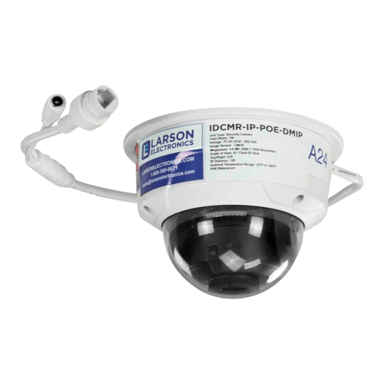
Vandalproof IP Dome Cameras
Quick Installation Guide
This document guides you through the basic steps to install and configure the IDCMR-IP-POE-DMIP
dome cameras.
These cameras feature:
2560 × 1920 resolution at 20 fps
•
H.265+ / H.265 / H.264OVC / H.264 / MJPEG compression
•
120 dB Wide Dynamic Range
•
120 ft Full Frame Illumination Smart IR array
•
Supports onboard storage up to 128GB Max microSD (card not included)
•
IP67, IK10 rated, −22 °F ~ 140 °F temperature range
•
ONVIF Profile S & Profile G, PSIA, CGI, ISAPI
•
Drop Cable
Mounting base
assembly
What's in the box
Your camera includes:
This document
•
Drill template
•
Waterproof Ethernet fitting
•
Mounting screws and wall inserts
•
Step 1.
Install the camera
The camera includes hardware to install it directly
to a ceiling (horizontal surface) or wall (vertical
surface). The cameara drop cable can be routed
through the mounting surface, or through the drop
cable channel in the base. To install the camera:
1.
Remove the dome cover. Unscrew the three
captive screws, and then lift the cover off of
the mounting base assembly. A tether cable
may be attached to the dome and the base
assembly.
2.
(Optional) Insert a microSD card in the slot. You can install a card with up to 128GB of storage.
1
www.larsonelectronics.com
Ethernet connector w PoE
Power connector
microSD card slot
and Reset button
Camera gimbal,
Tilt hold screw
Black liner
Lens
Dome cover
Dome cover
screw (3)
Mounting hardware
Weatherproof
Ethernet
Fitting
microSD card slot
RESET button*
* To restore the camera with its default configuration (including user name, password, IP address, etc.) press and hold the Reset
button for 10 s when the camera is power on or rebooting.
3.
Determine the best location for mounting the camera to the mounting surface. The mounting
surface should hold at least three times the weight of the camera.
4.
Determine the best fasteners for mounting the camera to the mounting surface. The mounting
hardware provided is adequate for many surfaces.
5.
Using the themplate provided or the camera mounting base as a template, mark the locations of
the holes for the mounting screws. Also mark the location of a hole for the camera drop cables
if needed.
6.
Drill holes into the mounting surface as needed. Also, drill a hole for the drop cable, if needed.
7.
Route extension cables from the power source and LAN switch (or LAN with PoE) to the
mounting location.
8.
Connect the network LAN and power extension cables to the camera drop cables:
a.
Connect the Ethernet LAN cable to the camera LAN drop cable. Protect the connection
from moisture and other contamination, if necessary. A Weatherproof Ethernet Fitting is
provided. Installation instructions for the fitting are included at the end of this document.
Camera
Network drop cable
from camera
Weatherproof Ethernet Fitting installed
Failure of the power or Ethnernet connector due to moisture or another
!
contaiminant is considered an installation error, which voids the waranty. If
installing this camera in a location such as an overhang, shop, garage, kitchen,
WARNING
etc. where high humidity or dust is present, seal these connections adequately.
b.
If the camera is not powered using PoE (Power over Ethernet injector), connect the 12 Vdc
power cable to the camera drop cable. The polarity of the drop cable connector is shown
below.
Do not apply power to the camera at this time. Before applying power to the camera, ensure
that the polarity is correct. An incorrect connection may cause a malfunction and can damage
CAUTION
the camera.
9.
Route the camera drop cable throught the cable channel in the base, or through the hole in the
mounting suface, and the secure the camera to the mounting surface using appropriate screws.
Mounting
surface
10.
Apply power to the camera through the 12 Vdc power cable or PoE injector, as configured.
Ethernet switch
Network cable from
router or switch
Mounting
screws (3)
IDCMR-IP-POE-DMIP
Advertisement
Table of Contents

Subscribe to Our Youtube Channel
Related Manuals for Larson Electronics IDCMR-IP-POE-DMIP


Summary of Contents for Larson Electronics IDCMR-IP-POE-DMIP
-
Page 1: Quick Installation Guide
Vandalproof IP Dome Cameras Quick Installation Guide This document guides you through the basic steps to install and configure the IDCMR-IP-POE-DMIP dome cameras. These cameras feature: 2560 × 1920 resolution at 20 fps • H.265+ / H.265 / H.264OVC / H.264 / MJPEG compression microSD card slot •... - Page 2 Step 2. Install the Tool Tool is a software utility used to “discover” cameras and NVRs/DVRs installed on the physical Ethernet network (LAN) and change their network settings. Tool is provided To use Discovery Tool: on Microsoft Windows computer you will use to access your camera on the LAN.
- Page 3 Step 3. Remote login When the following screen appears, click Run to download the plug-in (WebComponents) and continue. To access the camera from a computer on the LAN: Log into the operating system as a user with administrative privileges. Open the Microsoft Internet Explorer browser on your compute and enter the IP address of the When the following screen appears, click Run to install WebComponents.
- Page 4 Setup tab, and then click the Image link in the left frame. Log into the camera again to see the Live View - Main stream window. Live View image Adjust the Brightnessm Contrast, Saturation and Sharpness of the image as follows. Image Adjustment submenu (see above): Adjust the Saturation, Hue, Brightness, —...
-
Page 5: Specifications
Specifications Camera IDCMR-IP-POE-DMIP IR Range: Up to 120 ft (approx. 35 m) Camera IDCMR-IP-POE-DMIP Camera: Φ4.4” × 3.2” (Φ111 × 82.4 mm) Dimensions: Image Sensor: 1/2.9” Progressive Scan CMOS Package: 5.27” × 5.27” × 4.25” (134 × 134 × 108 mm)
Need help?
Do you have a question about the IDCMR-IP-POE-DMIP and is the answer not in the manual?
Questions and answers