Advertisement
Available languages
Available languages
Quick Links
These instructions contain IMPORTANT safety information. Please read and keep for future reference.
The user must read and understand these Instruction Sheets and the Warranty.
Installation is the end user's responsibility and beyond Horizon Global's control. Therefore, Horizon Global exclusively limits its Warranty to
the repair or replacement of a defective product. Damage to your vehicle, your cargo or any person or property is excluded.
•
Your bike carrier must be inspected for signs of wear, corrosion and fatigue before each use. DO NOT use if bent or deformed.
•
Make sure your bike carrier is secure before every trip. Check at each stop to ensure your bike carrier is secure.
•
DO NOT exceed your bike carrier's rated capacity. The capacity is listed on the next page.
•
Do not attempt to drill, weld, or modify your bike carrier or any of the system components.
•
This carrier is designed for typical use and applications (on paved or smooth gravel roads). Do not use this carrier on a vehicle that
will be driven on rough roads, or where the carrier (and bikes) will be subjected to significant or constant jarring and/or shock, or any
vehicle with very stiff springs that will transfer the load shocks directly to the carrier and the bikes.
•
The recommended minimum ground clearance is 14". This may not be sufficient ground clearance depending on the application.
Damage to bicycles or carrier due to ground clearance problems are not covered by warranty.
•
Bike tires should be at least 6 inches away from exhaust pipe.
•
DO NOT use this bike carrier with recreational vehicles, trailers or in off road situations.
•
DO NOT use your bike carrier for purposes other than those for which it was designed.
•
REDUCE YOUR SPEED. Your vehicle can handle differently when transporting bicycles.
•
FREQUENTLY check your bike carrier and that the bikes are secure. Bikes can shift or your bike carrier can loosen during travel.
Readjust as needed. If movement continues, stop use.
•
ALWAYS unload bikes before removing your bike carrier from hitch.
•
Check local and state laws governing projection of objects beyond the perimeter of a vehicle.
•
ALWAYS obey all posted speed limits and be aware of traffic conditions. Adapt your speed to the conditions of the road and the load
being carried.
•
The proper attachment of this product in accordance with the enclosed instructions is critical to its proper performance. See
instructions for proper attachment, proper usage, and important safety messages. Horizon Global, Inc. has no control over, or
responsibility for, the attachment or the installation. Horizon Global, Inc. is NOT responsible nor will it be held liable for any damage
resulting from its attachment or improper use. Horizon Global, Inc. shall not be liable for any claims of any kind greater than the
purchase price of the product. Warranty information available upon request.
•
NOTICE: Your bike carrier will not prevent property damage that may result from improper loading, securing, or driving. Insure all
locks are locked, that all pins are secured, and that all straps are properly attached prior to moving the vehicle.
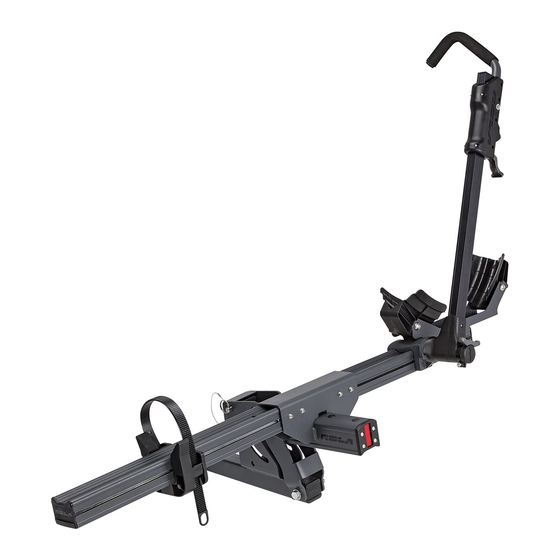
INSTRUCTION GUIDE FOR:
CONVOY MODULAR BIKE CARRIER
59307 (1-1/4 in. Hitch)_59308 (2 in. Hitch)_59310 (Add-on Unit)
Date of Purchase:
WARNING
Review all Warnings, Instructions, and Warranty information carefully.
Failure to follow these warnings and instructions will void the Warranty.
Call Technical Services at (800) 234-6992 or go to RolaProducts.com, if you have
any questions regarding the use or the limits of your bike carrier. For assistance
with this product or to order replacement parts, please contact
Horizon Global, 47912 Halyard Drive Suite 100, Plymouth, MI 48170
Questions? (800) 234-6992 • RolaProducts.com
PAGE 1
PAGE 1
59307_59308_59310_IN_Rev A • Questions? (800) 234-6992 • RolaProducts.com
5910200_Rev A • Questions? (800) 239-6992 • RolaProducts.com
/
/
Advertisement

Subscribe to Our Youtube Channel
Related Manuals for Rola 59307


Summary of Contents for Rola 59307
- Page 1 INSTRUCTION GUIDE FOR: CONVOY MODULAR BIKE CARRIER 59307 (1-1/4 in. Hitch)_59308 (2 in. Hitch)_59310 (Add-on Unit) Date of Purchase: These instructions contain IMPORTANT safety information. Please read and keep for future reference. WARNING The user must read and understand these Instruction Sheets and the Warranty.
-
Page 2: Unit Capacity
CAPACITY HITCH CAPACITY UNIT CAPACITY 59307 1-1/4 IN. HITCH MOUNT Pages 4-9 EACH UNIT (59307, 59308, and 59310) holds: MAXIMUM CAPACITY PER BIKE • Bikes with up to 48 in. wheel bases base UNIT PART DESCRIPTION 1 Bike 2 Bike •... -
Page 3: Parts List
Tools required for assembly (all included): (1) 4mm allen wrench, (1) 8mm allen wrench, (1) 19mm wrench. PART DESCRIPTION QTY. 59307 1-1/4 in. BASE UNIT 59308 2 in. BASE UNIT 59310 ADD ON UNIT Single Bike Center Support Single Bike Center Support... - Page 4 ASSEMBLY INSTRUCTIONS 59307 1-1/4 in. / 59308 2 in. Base Units Base unit-Single bike center support CENTER SUPPORT ASSEMBLY Assembly is shown using vehicle receiver. If vehicle is not available, assembly can be done on ground or table. 1. Slide single bike center support (A or B) into vehicle receiver. Secure 12mm anti-rattle hitch pin bolt (J) with either 19mm wrench (M) or 8mm allen wrench (N).
- Page 5 ASSEMBLY INSTRUCTIONS 59307 1-1/4 in. / 59308 2 in. Base Units Arm assembly grip ARM ASSEMBLY Grip lever 1. Slide arm assembly grip (H) onto rotating arm assembly (G) with grip lever on same side as detents. Fig 1. Rotating arm assembly Detents 2.
- Page 6 ASSEMBLY INSTRUCTIONS 59307 1-1/4 in. / 59308 2 in. Base Units ROTATING ARM ASSEMBLY FUNCTIONS 1. Locked positions: - When not in use: Position 1 - Frame hold: Position 2 - When not in use: Position 3 2. Wheel hold positions:...
- Page 7 ASSEMBLY INSTRUCTIONS 59307 1-1/4 in. / 59308 2 in. Base Units Rotating arm assembly release ROTATING ARM ASSEMBLY FUNCTIONS (continued) 1. To release rotating arm assembly from locked position, pull rotating arm assembly release outward. FIG 1. Grip trigger 2. To lower grip, pull grip downward. FIG 2.
- Page 8 ASSEMBLY INSTRUCTIONS 59307 1-1/4 in. / 59308 2 in. Base Units Grip Grip triger Maximum height LOADING BIKES Grip lever Securing by the front wheel: 1. Be sure rotating arm assembly (G) is on the front cradle tube side (D).
- Page 9 ASSEMBLY INSTRUCTIONS 59307 1-1/4 in. / 59308 2 in. Base Units LOADING BIKES (continued) Grip Grip triger Maximum height Securing by the frame: Grip lever 1. Be sure rotating arm assembly (G) is on the rear cradle tube side (E).
- Page 10 ASSEMBLY INSTRUCTIONS 59310 Add-on Unit ADD-ON CARRIER ASSEMBLY Base unit: Front wheel 1. Assembly for add-on unit will be in the OPPOSITE direction of the base tube with cradle-right unit that this add-on unit is being connected to. FIG 1. Add-on unit: 2.
- Page 11 ASSEMBLY INSTRUCTIONS 59307 1-1/4 in. / 59308 2 in. Base Units / 59310 Add-on Unit RAISING OR LOWERING CARRIER 1. Carrier can tilt upward when empty for added clearance or when removing from vehicle. To tilt carrier upward, pull locking pin, tilt upward and reinstall locking pin in lower hole to secure.
- Page 12 ASSEMBLY INSTRUCTIONS 59307 1-1/4 in. / 59308 2 in. Base Units / 59310 Add-on Unit CRADLE STRAPS Strap placement for transport or storage: To avoid damaging or loosing strap when storing or transporting an empty carrier, fold strap through slot on the bottom of the rear cradle. FIG 1.
- Page 13 MODE D’EMPLOI POUR : SUPPORT POUR BICYCLETTE MODULAIRE CONVOY 59307 (Attelage de 1 po) _59308 (Attelage de 2 po) _59310 (Unité complémentaire) Date d’achat : Ces instructions contiennent des consignes de sécurité IMPORTANTES. Lisez-les et conservez-les pour référence future. AVERTISSEMENT WARNING L’utilisateur doit lire et assimiler ces pages d’instructions et la garantie.
- Page 14 CAPACITÉ DE L’ATTELAGE CAPACITÉ DE L’UNITÉ 59307 PORTE-ATTELAGE DE 1,25 PO Pages 4 à 9 CHAQUE UNITÉ (59307, 59308, et 59310) peut porter : CAPACITÉ MAXIMALE PAR VÉLO • Bicyclettes avec bases de roue jusqu’à 48 po UNITE ´ DE BASE PART PIÈCE...
-
Page 15: Instructions D'assemblage
Outils requis pour l’assemblage (inclus) : Une (1) clé Allen de 4 mm, une (1) clé Allen de 8 mm, une (1) clé de 19 mm. PIÈCE DESCRIPTION QTÉ 59307 1,25 po UNITÉ DE 59308 2 po UNITÉ DE BASE 59310 UNITÉ BASE COMPLÉMENTAIRE... - Page 16 INSTRUCTIONS D’ASSEMBLAGE 59307 1,25 po. / 59308 2 po. Unités de base Unité de base - Support unique du centre de la bicyclette ENSEMBLE DE SOUTIEN DU CENTRE L’ensemble est illustré en utilisant le réceptacle du véhicule. Si le véhicule n’est pas disponible, l’assemblage peut se faire sur le sol ou une table.
- Page 17 INSTRUCTIONS D’ASSEMBLAGE 59307 1,25 po. / 59308 2 po. Unités de base Poignée de l’ensemble du bras ENSEMBLE DU BRAS Levier de poignée 1. Faites glisser la poignée de l’ensemble de bras (H) sur l’ensemble de bras rotatif (G) avec le levier de la poignée du même côté que les Ensemble de bras rotatif crans.
- Page 18 INSTRUCTIONS D’ASSEMBLAGE 59307 1,25 po. / 59308 2 po. Unités de base FONCTIONS DE L’ENSEMBLE DE BRAS ROTATIF 1. Positions verrouillées : - Lorsque l’attelage n’est pas utilisé : Position 1 - Soutien du cadre : Position 2 - Lorsque l’attelage n’est pas utilisé : Position 3 2.
- Page 19 INSTRUCTIONS D’ASSEMBLAGE 59307 1,25 po. / 59308 2 po. Unités de base Levier de dégagement de l’ensemble de bras rotatif FONCTIONS DE L’ENSEMBLE DE BRAS ROTATIF (suite) 1. Pour relâcher l’ensemble de bras rotatif de la position verrouillée, tirez le verrou de l’ensemble de bras rotatif vers l’extérieur. FIG. 1.
- Page 20 INSTRUCTIONS D’ASSEMBLAGE 59307 1,25 po. / 59308 2 po. Unités de base CHARGEMENT DES BICYCLETTES Verrouillage par la roue avant : 1. Assurez-vous que l’ensemble de bras rotatif (G) se trouve sur le Hauteur maximale Détente de poignée de la poignée côté...
- Page 21 INSTRUCTIONS D’ASSEMBLAGE 59307 1,25 po. / 59308 2 po. Unités de base CHARGEMENT DES BICYCLETTES (suite) Verrouillage par le cadre : 1. Assurez-vous que l’ensemble de bras rotatif (G) se trouve sur le côté du tube du dispositif d’attache arrière (E). Voir page 6, figure 4a Hauteur maximale pour référence.
- Page 22 INSTRUCTIONS D’ASSEMBLAGE 59310 Unité complémentaire ENSEMBLE DE SUPPORT COMPLÉMENTAIRE Unité de base : Tube de roue avant 1. L’ensemble de l’unité complémentaire sera dans la direction OPPOSÉE avec dispositif d’attache - droite à celle de l’unité de base à laquelle ladite unité complémentaire est Unité...
- Page 23 INSTRUCTIONS D’ASSEMBLAGE 59307 1,25 po. / 59308 2 po. Unités de base / 59310 Unité complémentaire SOULEVER OU ABAISSER LE SUPPORT 1. Le support peut basculer vers le haut lorsqu’il est vide pour créer de l’espace supplémentaire ou le retirer du véhicule. Pour incliner le support vers le haut, retirez la goupille de verrouillage, inclinez-la vers le haut et réinstallez-la dans le trou inférieur pour la fixer.
- Page 24 INSTRUCTIONS D’ASSEMBLAGE 59307 1,25 po. / 59308 2 po. Unités de base / 59310 Unité complémentaire SANGLES DU DISPOSITIF D’ATTACHE Position de la sangle pour le transport ou le stockage : Pour éviter d’endommager ou de perdre de la sangle lors du stockage ou du transport d’un support vide, repliez la sangle dans la fente au bas du...
- Page 25 GUÍA DE INSTRUCCIONES PARA: CANASTILLA MODULAR PARA BICICLETAS EN CONVOY 59307 (Gancho de 1-1/4 in)_59308 (Gancho de 2 in)_59310 (Unidad adicional) Fecha de compra: Estas Instrucciones contienen información IMPORTANTE de seguridad. Leer y conservar para referencia futura. ADVERTENCIA WARNING El usuario debe leer y comprender estas Hojas de instrucciones y la Garantía.
- Page 26 CAPACIDAD CAPACIDAD DE LA UNIDAD CAPACIDAD DEL GANCHO CADA UNIDAD (59307, 59308, y 59310) sujeta: 59307 MONTURA CON GANCHO DE 1-1/4 IN Páginas 4 a 9 • Bicicletas con bases de rueda de hasta 48 in CAPACIDAD MÁXIMA POR BICICLETA •...
-
Page 27: Instrucciones De Ensamblaje
Herramientas requeridas para el ensamble (todo incluido): (1) llave Allen de 4 mm, (1) llave Allen de 8 mm, (1) llave de 19 mm. PARTE DESCRIPCIÓN CANT. 59307 1-1/4 in. UNIDAD BASE 59308 2 in. UNIDAD BASE 59310 UNIDAD ADICIONAL Soporte central individual para bicicleta... -
Page 28: Instrucciones De Ensamble
INSTRUCCIONES DE ENSAMBLE 59307 1-1/4 in. /59308 2 in. Unidades base Unidad base-Soporte central individual para bicicleta ENSAMBLE DE SOPORTE CENTRAL El ensamble se muestra utilizando el receptor del vehículo. Si el vehículo no está disponible, el ensamble se puede realizar en tierra o sobre una mesa. - Page 29 INSTRUCCIONES DE ENSAMBLE 59307 1-1/4 in. /59308 2 in. Unidades base Manija del ensamble del brazo ENSAMBLE DEL BRAZO Palanca de la manija 1. Deslice la manija del ensamblaje del brazo (H) sobre el ensamble del brazo giratorio (G) con la palanca de la manija en el mismo lado que Ensamble del brazo giratorio los retenes.
- Page 30 INSTRUCCIONES DE ENSAMBLE 59307 1-1/4 in. /59308 2 in. Unidades base FUNCIONES DEL ENSAMBLE DEL BRAZO GIRATORIO 1. Posiciones bloqueadas - Cuando no se usa: Posición 1 - Sujetar por el marco: Posición 2 - Cuando no se usa: Posición 3 2.
- Page 31 INSTRUCCIONES DE ENSAMBLE 59307 1-1/4 in. /59308 2 in. Unidades base Liberación del ensamble del brazo giratorio FUNCIONES DEL ENSAMBLE DEL BRAZO GIRATORIO (continuación) 1. Para liberar el ensamble del brazo giratorio de la posición de bloqueo, tire del dispositivo de liberación del ensamble del brazo giratorio hacia Gatillo de la manija afuera.
- Page 32 INSTRUCCIONES DE ENSAMBLE 59307 1-1/4 in. /59308 2 in. Unidades base CÓMO CARGAR LAS BICICLETAS Cómo sujetarse por la rueda frontal: Altura Gatillo de la manija 1. Asegúrese de que el ensamble del brazo giratorio (G) esté en la parte máxima de la manija...
- Page 33 INSTRUCCIONES DE ENSAMBLE 59307 1-1/4 in. /59308 2 in. Unidades base CÓMO CARGAR LAS BICICLETAS (continuación) Cómo sujetarse por el bastidor: Altura 1. Asegúrese de que el ensamble del brazo giratorio (G) esté en la parte Gatillo de la manija máxima de la manija...
- Page 34 INSTRUCCIONES DE ENSAMBLE 59310 Unidad adicional ENSAMBLE DE LA CANASTILLA ADICIONAL Unidad base: Tubo de la rueda 1. El ensamble de la unidad adicional estará en la dirección OPUESTA de frontal con base de apoyo, der. la unidad base a la cual se conectará esta unidad adicional. FIG. 1. Unidad adicional: 2.
- Page 35 INSTRUCCIONES DE ENSAMBLE 59307 1-1/4 in. /59308 2 in. Unidades base/59310 Unidad adicional CÓMO LEVANTAR O BAJAR LA CANASTILLA 1. La canastilla puede inclinarse hacia arriba cuando está vacía para ofrecer mayor espacio libre o al retirarse del vehículo. Para inclinar...
- Page 36 INSTRUCCIONES DE ENSAMBLE 59307 1-1/4 in. /59308 2 in. Unidades base/59310 Unidad adicional CORREAS DE LAS BASES DE APOYO Colocación de la correa para el transporte o almacenamiento: Para evitar dañar o perder la correa al almacenar o transportar una canastilla vacía, doble la correa a través de la ranura de la parte inferior de...
Need help?
Do you have a question about the 59307 and is the answer not in the manual?
Questions and answers