Carel MasterCella Technical Leaflet
Hide thumbs
Also See for MasterCella:
- User manual (56 pages) ,
- User manual (56 pages) ,
- User manual (60 pages)
Table of Contents
Advertisement
Available languages
Available languages
Advertisement
Table of Contents

Subscribe to Our Youtube Channel
Related Manuals for Carel MasterCella


Summary of Contents for Carel MasterCella
- Page 1 MasterCella Prospect tehnic Technical leaflet...
- Page 2 CAREL can not be held responsible. The final client must use the product only in the manner described in the documentation related to the product itself. The liability of CAREL in relation to its...
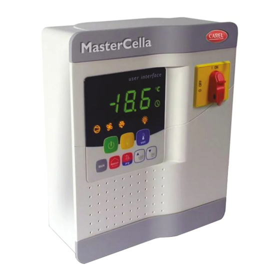
- Page 3 3. DISPLAY Mastercella este prevazut cu display cu LED, 3 digiti, pentru afisarea temperaturii si cu iconite pentru afisarea functionarii instalatiei. Poate fi conectat, folosind o interfata speciala, la un display suplimentar, folosit, de exemplu, pentru vizualizarea temperaturii din sonda 3.
- Page 4 Functia HACCP MasterCella are implementata aceasta functie in standard, pentru a monitoriza temperatura din depozitul de alimente. Alarma “HA”=depasirea pragului maxim: in plus, pana la trei tipuri de alarme HA sunt salvate (HA, HA1, HA2), respective de la cea mai recenta (HA) pana la cea mai veche (HA2), cu un semnal Han care afiseaza numarul de alarme HA.
- Page 5 Aceasta ete o procedura speciala care foloseste o aplicatie instalata pe PC pentru setarea simpla si controlul adreselor seriale a tuturor echipamentelor (caracteri- stica a acestei functii) conectate la o retea CAREL. Procedura este extreme de simpla: Folosind softul de la distanta, porniti procedura “Network definition”; procedura porneste trimitand un mesaj special (‘<ADR>’) la reteaua CAREL, care contine adrese in retea;...
- Page 6 Tab. 3.c Configurare sensor (/A2 la /A4) La seria MasterCella, acesti parametric sunt folositi pentru configurarea modului senzorului: 0 = fara senzor; 1 = sensor produs (doar vizualizare); 2= sensor degivrare; 3 = sensor condensare; 4 = sensor anti-inghet. Configurarea intrarii digitale (A4,A5) La MasterCella, acest parametru si modelul de controller folosit definesc functionalitatea intrarii digitale: 0 = intrare neactivata;...
- Page 7 4. CUPRINSUL PARAMETRILOR FUNCTIONALI UOM = unitate de masura; Def. = val. implicita Simbol Cod. Parametru U.M. Deg. Parola stabilitatea masuratorii rata afisarii senzorului senzor virtual selectati °C sau °F flag 0: °C 1: °F Punct zecimal flag Cu zecimi de un grad Fara zecimi de un grad vizualizare pe terminal intern 1: sensor virtual...
- Page 8 Simbol Cod. Parametru U.M. Deg. intarzierea releului compressor, vent, si AUX la pornire, la control cu banda moarta AD timpul minim intre doua porniri succesive timp minim repaus compresor timp minim functionare compresor setarea functonarii perioada ciclului continuu intarzierea alarmei dupa ciclu continuu timpul maxim de Pump-Down intarzierea pornirii compresorului dupa functionarea valvei PD activarea functiei autostart cu functionare PD...
- Page 9 8: Presostat de joasa presiune 9: Oprirea doar a ventilatoarelor la deschiderea usii 10: Functionare directa/inversa 11: Senzor lumina 12: Activarea iesirii auxiliare AUX 13: Oprirea compresorului si ventilatoarelor la deschiderea usii si controlul luminii 14: Oprirea doar a ventilatoarelor la deschiderea usii fara controlul luminii configurarea ID 2 Idem A4 oprire compressor sau alarma externa...
- Page 10 activare cod pentru telecomanda dezactivarea buzzer flag 0: Sonerie activata 1: Sonerie dezactivata functia releu 5 flag Idem H1 blocare tastatura selectare activare iesire cu banda moarta flag 0: Cu legatura la iesirea configurata la iluminat 1: Cu legatura la iesirea configurata la auxiliar activare variatia setpoint cu banda moarta flag 0: Variatia setointului cand este Dezactivata...
- Page 11 5. TABELUL CU ALARME SI SEMNALE: vizualizare, buzzer si relee Urmatorul table descrie alarmele si semanlele de pe controller, cu descrierea corespunzatoare, starea buzzerului, releul de alarma si modul de resetare. Iconita de pe display Releu de alarma Buzeer Reset Descriere ‘rE’...
- Page 12 3. DISPLAY MasterCella is fitted with a three digit LED display for the temperature, and icons for displaying the operating status. It can also be connected, using a special interface, to a further display, used, for example, to show the reading of the third probe.
- Page 13 HACCP function MasterCella is compliant with the HACCP standards, as it monitors the temperature of the food stored. Alarm “HA”= maximum threshold exceeded: in addition, up to three HA events are saved (HA, HA1, HA2), respectively from the most recent (HA) to the oldest (HA2), with a signal HAn that displays the number of HA events that have occurred.
- Page 14 This is a special procedure that uses an application installed on a PC to simply set and manage the addresses of all the instruments (that feature this function) connected to the CAREL network. The procedure is very simple: 1) Using the remote software, start the “Network defi nition” procedure; the application starts sending a special message (‘<!ADR>’) to the CAREL network, containing the network address;...
- Page 15 Probe confi guration (/A2 to /A4) In the MasterCella series, these parameters are used to confi gure the operating mode of the probes: 0 = probe absent; 1 = product probe (display only); 2 = defrost probe; 3 = condenser probe; 4 = antifreeze probe.
- Page 16 4. SUMMARY OF OPERATING PARAMETERS UOM = Unit of measure; Def. = Default value Simbol Code Parameter U.O.M. Type Def. Password Measurement stability Probe display response Virtual probe Select °C or °F flag 0: °C 1: °F Decimal point flag with tenths of a degree without tenths of a degree Display on internal terminal...
- Page 17 Simbol Code Parameter U.O.M. Type Def. Comp., fan and AUX delay on start-up in dead band Minimum time between successive starts Minimum compressor OFF time Minimum compressor ON time Duty setting Continuous cycle duration Alarm bypass after continuous cycle Maximum pump down time Comp.
- Page 18 8: Low pressure switch 9: Door switch with fan stop only 10: Direct/reverse 11: Light sensor 12: Activation of the AUX output 13: Door switch with compressor and fans off and light not managed 14: Door switch with fans only off and light not managed Digital input 2 configuration As for A4 Stop compressor from external alarm...
- Page 19 Remote control enabling code Disable buzzer flag 0: Buzzer enabled 1: Buzzer disabled Function of relay 5 flag As for H1 Lock keypad Select activation of output with time band flag 0: Time band linked to output configured for light 1: Time band linked to output configured for aux Enable set point variation with time band flag...
- Page 20 5. TABLE OF ALARMS AND SIGNALS: display, buzzer and relay The following table describes the alarms and the signals on the controller, with the corresponding description, status of the buzzer, the alarm relay and the reset mode. Code Icon on the display Alarm relay Buzzer Reset...
- Page 21 10kΩ a 25°C, range from –50°C to +90°C 1°C in the range from –50° C to +50°C NTC std. CAREL measurement error: 3°C in the range from +50° C to +90°C 50kΩ a 25°C, range from –40°C a +150°C Probe type 1,5°C in the range from –20°...
- Page 22 Software class and structure Class A Front panel cleaning use only neutral detergents and water Serial interface for CAREL network external, available on all models Interface for repeater external, available on IRxxxx(0,L,H)xxxx display Maximum distance betwe-...
- Page 23 7. RECOMMENDED CURRENT ACCORDING TO THE CROSS-SECTION OF THE WIRES Cross-section (mm Current 0.21 0.26 0.33 0.41 0.52 0.65 0.82 1.31 1.65 2.63 12.8 3.31 16.1 Tab. 6.a 8. CONFIGURATIA ELECTRICA/ELECTRICAL CONFIGURATIONS/ BRANCHEMENTS ÉLECTRIQUES/ELEKTRISCHE ANSCHLÜSSE/CONEXIONES ELÉCTRICAS/LIGAÇÕES ELECTRICAS MD33(A,D) (0,1,2,3,4,5) (A,B,E,F) (N,R,C,B) (0,1,2,3,4,5,6,7) 0 Fig.
- Page 24 Fig. 7.b +050004104 rel. 2.2 del 26.09.07...
- Page 25 9. EXEMPLU DE CONEXIUNI TERMINALE/EXAMPLES OF TERMINAL BOARDS CONNECTION/EXEMPLE DE CÂBLAGE DE LA CARTE DE CONNE- XION/ANSCHLUSSBEISPIEL FUER DIE STECKVERBINDUNGEN/EJEMPLOS DE CONEXIÓN TARJETAS BORNES/EXEMPLO DI LIGAÇÃO DA PLACA DE CONECTORES Fig. 8.a +050004104 rel. 2.2 del 26.09.07...
- Page 26 Fig. 8.b +050004104 rel. 2.2 del 26.09.07...
- Page 27 10. DIMENSIUNI/DIMENSIONS/DIMENSIONS/ABMESSUNGEN/ DIMENSIONES/DIMENSÕES Fig. 9.a +050004104 rel. 2.2 del 26.09.07...
- Page 28 Agenzia/Agency CAREL INDUSTRIES - HQs Via dell’Industria, 11 - 35020 Brugine - Padova (Italy) Tel. (+39) 049.9716611 - Fax (+39) 049.9716600 e-mail: carel@carel.com - www.carel.com...
Need help?
Do you have a question about the MasterCella and is the answer not in the manual?
Questions and answers