
Related Manuals for Carel MuC2SE


Summary of Contents for Carel MuC2SE
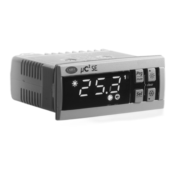
- Page 1 µC SE for process chiller Electronic controller User manual I n t e g r a t e d C o n t r o l S o l u t i o n s & E n e r g y S a v i n g s...
- Page 3 The client (builder, developer or installer of the final equipment) assumes every responsibility and risk relating to the configuration of the product in order to reach the expected results in relation to the specific final installation and/or equipment. CAREL in this case, through specific agreements, can intervene as consultant for the positive result of the final start-up machine/application, but in no case can it be held responsible for the positive working of the final equipment/apparatus.
- Page 4 µC SE process chiller +030220416 - rel. 2.3 - 17.05.2018...
-
Page 5: Table Of Contents
Content INTRODUCTION ........................7 1.1 General description ..............................7 1.2 Codes ..................................7 1.3 Accessories ................................7 INSTALLAT ..........................9 2.1 Type of fixing and dimensions ............................ 9 2.2 Operational layouts ..............................9 2.3 μC SE Wiring diagram ............................. 10 2.4 I/O board Wiring diagram ............................ - Page 6 µC SE process chiller +030220416 - rel. 2.3 - 17.05.2018...
-
Page 7: Introduction
INTRODUCTION General description μC SE for process chiller is a compact electronic controller designed for the complete management of the process chiller with 1 refrigerating circuit: it can control air-water and water-water machines. The controller has 5 digital inputs, 5 digital outputs, 4 analogue inputs and 1 analogue output. It can be installed: individually;... - Page 8 (MCH200TW00). For further information see the instruction sheet +050001065. Programming key (code PSOPZKEY*0) The programming keys PSOPZKEY00 and PSOPZKEYA0 for CAREL controllers allow the copying of the complete set of parameters of the μC SE. The keys must be connected to the connector (AMP 4 pin) envisioned in the controllers and can operate with controllers powered or not.
-
Page 9: Installat
INSTALLAT Type of fixing and dimensions μC SE for process chiller is supplied with connectors of different format to facilitate the electric connections. The EVD driver and the I/O board must be installed on DIN guide. Dimensions (mm) Operational layouts Below find the structure of the tLAN network, with the μC SE controller for process chiller, which can operate alone or with the I/O expansion board. -
Page 10: Μc 2 Se Wiring Diagram
μC SE Wiring diagram 24 Vac power supply Power supply reference B1…B4 Analogue inputs 1…4 ID1…ID5 Digital inputs 1…5 C1…C5 Common digital outputs 1…5 NO1…NO5 Digital outputs 1…5 normally open contact Analogue output 1 Key/SPV Connector for key/supervisor Ratiometric pressure probe power supply Tx/Rx tLAN port Ground... -
Page 11: Connection With Conv0/10Va0 And Convonoff0 Modules (Accessories)
Connection with CONV0/10VA0 and CONVONOFF0 modules (accessories) The CONV0/10AVA0 and CONVONOFF0 modules allow to convert a PWM output for SSR respectively into an analogue output 0…10Vdc and into an ON/OFF output with relay. Note that with the same controller 3 different types of outputs can be obtained. CONV0/10A0 - CONVONOFF0 module CONV0/10A0 module CONVONOFF0 module... -
Page 12: Programming Key (Copy Of The Set-Up)
The protection against short circuits due to faulty wiring must be guaranteed by the manufacturer of the appliance that the controller will be fitted on. Programming key (copy of the set-up) The PSOPZKEY00 and PSOPZKEYA0 programming keys for CAREL controllers allow to copy the complete set of μC SE parameters. The keys must be connected to the connector (AMP 4 pin) envisioned in the controllers and can operate with instruments that are live or not, according to that indicated in the user notes of the specific controller. - Page 13 The operation is completed in 10 seconds. If the completed signal with green LED on is not given within this time period, it is good practice to attempt the operation again, releasing and pressing the button again. In the event of flashing, see the relative table for the meaning of the signal. signal error meaning and solution...
-
Page 14: User Interface
USER INTERFACE The front panel contains the display and keyboard, made up from 4 keys, which, pressed individually or together, allow to perform all of the controller programming operations. Display The display features 3 digits, with the display of the decimal point between -99.9 and 99.9. Outside of this range of measurement, the value is automatically displayed without the decimal (even if internally the unit still operates considering the decimal part). -
Page 15: Menu Structure
Levels “Factory”: accessible with password 66, it allows the configuration of all unit parameters; “Super User”: accessible with password 11, it allows the configuration of the Super User, User and Direct parameters; “User”: accessible with password 22, it allows the configuration of those parameters that can be set typically by the user and Direct, therefore relative to the options. -
Page 16: Commissioning
5 new warnings or alarms. Moreover, it allows each individual digital output to change on the basis of an individual alarm. The serial address identifies the controller in a RS485 network with Carel or Modbus protocol. -
Page 17: Minimum And Maximum Fan Speed Calculation
Other configuration parameters (par. c14, /23, H09, P35) c14 establishes the number of operating hours of the compressors/pumps, expressed in hundreds of hours, over which to activate the maintenance request signal (Hc1, Hc2). c10 and c11 are read only parameters and indicate the number of operating hours of the compressors 1 and 2, expressed in hundreds of hours. -
Page 18: Functions
FUNCTIONS 5.1 Set point The control algorithm is the ON/OFF type according to the figure. The set point r01 can be set from a minimum value to a maximum value (par. r13, r14). The probe selected for the control depends on parameter r06, once enabled with the parameters /01 and /02. If r06 = 0,1 the probe is B1. If r06 = 2, 3, 4 the control probe is B2. -
Page 19: Probe Reading
The probes B1/B2 have the function of input/output evaporator temperature. The probe B3 can be configured as condensation temperature probe, external or differential control. The external probe allows the activation of the external compensation algorithm. The probe B4 can have the same functions as B3 and in addition acts as digital input (can be configured from par. -
Page 20: Digital Outputs
The warnings/alarms Ad1...Ad5 can be used to switch-over the outputs NO11,..NO15 of the I/O expansion board, along with the high pressure, low pressure alarms, etc. See parameter P42 at the "Digital outputs" paragraph. Par. Description U.M. Digital input 1 0=Not used 1=Flow switch alarm with manual reset 2=Flow switch alarm with automatic reset 3=General thermal overload alarm with manual reset... -
Page 21: Analogue Outputs
Analogue outputs The analogue output Y1 is set-up for the condenser fan and is active if F01 = 1. In systems with hot gas bypass function enabled, the bypass valve is commanded by the output Y1 (controller) or Y2 (I/O expansion board). See the control chapter. 5.7 Compensation The compensation can indifferently increase or decrease the value of r01 depending on whether r17 is respectively positive or negative. -
Page 22: Control
CONTROL Anti-freeze The anti-freeze probe is B2. The anti-freeze set-point A01 represents the temperature below which the machine passes to anti-freeze mode: alarm A1 activates and switches the alarm output. The value of A01 is limited by A07. A03 is the intervention delay time of the anti-freeze alarm when starting the machine. - Page 23 Protection for outputs with different relays (par. c04, c05) c04 establishes the minimum time that must pass between successive switch-ons of 2 compressors. By delaying the connection, line overloads are prevented due to close or simultaneous peaks, c05 establishes the minimum time that must pass between the switch-off of the two compressors. Par.
- Page 24 r06 = 0: proportional input r06 = 2: proportional output CMP1 CMP1 CMP2 CMP1 CMP1 CMP2 r06 = 1: proportional input + neutral zone r06 = 3: proportional output + neutral zone CMP1 CMP1 CMP2 CMP1 CMP1 CMP2 Set point Time Neutral zone differential CMP1/2...
-
Page 25: Pumps Management
Compressors deactivation external temperature (par.r25) The compressors are deactivated if the external temperature drops below the value of r25. The differential for re-activation is fixed at 1 degree. The resistances can be activated according to the relative set-points Par. Description U.M. -
Page 26: Fan Management
6.7 Fan management Fan operation F01 enables the condenser fan output, according to the output assigned by parameter H11. Depending on the type of fan, the controller PWM output (Y1), always active, requests the presence of optional boards: 1) CONVONOFF0 for the conversion of the PWM output into ON/OFF output; 2) CONV0/10A0 for the conversion of the PWM output into 0…10 Vdc or 4…20 mA output;... -
Page 27: Hot Gas Bypass
6.8 Hot gas bypass The hot gas by-pass in temperature mode function allows to increase the temperature of the output water from the evaporator. The output enabled is the controller analogue output Y1 (water-water chiller) or Y2 (air-water chiller) of the I/O expansion board. Par. -
Page 28: Parameter Table
Variable type: A = analog; D = digital; I = Integer Par. Description Level U.M. DEF. Disp. SVP CAREL ModBus® R/W Variable type Probes setting parameters: /* Probe B1 0/1 = Absent/ Present Probe B2 0/1 = Absent/ Present Probe B3... - Page 29 Pump down minimum pressure Pump down maximum time Default parameters setting: 0 = enabled; 1 = disabled Network protocol: 0 = Carel; 1 = ModBus High/low temperature alarm effect 0 = No compressor stop 1 = Stop due to high temperature alarm...
- Page 30 Par. Description Level MIN U.M. DEF. Disp. SVP Carel ModBus® R/W Variable type Alarms setting parameters: P* Flow switch alarm delay at pump start-up R/W I Flow switch alarm delay in normal conditions R/W I Low pressure alarm delay at compressor start-up...
-
Page 31: Variables Accessible Only By Supervision
Par. Description Level U.M. DEF. Disp. SVP Carel ModBus® Variable type Regulation setting parameters: r* Set point °C/°F 12.0 Differential °C/°F Compressors rotation 0 = Disabled 1 = FIFO type 2 = Hours balancing 3 = Do not select Type of regulation/compressors use... -
Page 32: Alarms
ALARMS Type of alarms The alarms cause the LED on the display to switch on. There are two types: • serious: they cause the total switch-off of the controller: e.g. high power supply voltage, communication error with I/O expansion board; •... -
Page 33: Alarm Description
Alarm Alarm type Reset Compressor Pump Heater Exp. Output I/O exp. Superv. Superv. variab. Variable display valve alarm board variable description type Dig. input 13 alarm Manual √ 88 (R)** OUT 13 state Digital Dig. input 14 warning Manual √ 89 (R)** OUT 14 state Digital... - Page 34 E1...E4: probe error detected also with machine in Stand-by. The presence of a probe alarm leads to the deactivation of the compressor, the condenser fan, pump and heater; the alarm relay and display flashing are activated. In the event of external probe fault and compensation function enabled, the unit continues to operate correctly, the function deactivates, a warning is activated via the alarm relay and the message appears on the display from E1 to E4 for probes B1 to B4.
-
Page 35: Alarm Digital Inputs/Outputs
AHt: high temperature on plant switch-on warning. The warning does not activate the relay and displays the "AHt" message. ALt: low temperature on plant switch-on warning. The warning does not activate the relay and displays the "Alt" message. ELS/EHS: warning low/alarm high power supply voltage warning. If the power supply voltage is too high or too low, the relative message appears on the display. -
Page 36: Technical Specifications
CAREL NTC temperature probes (10 kW at 25 °C) Response time depends on the component used, typical value 90 s. B4: NTC temp. probes (10 kW at 25 °C) or ratiom. pressure probes CAREL 0...5 V SPK*00**R* Fan output Control signal for CAREL modules MCHRTF****, CONVONOFF* and CONV0/10A* Impulse position modulation (settable width) or modulation of the duty cycle Unloaded voltage: 5 V ±... -
Page 37: Software Releases
Contact Molex® code Cable section allowed 39-00-0077 AWG16 (1.308 mm2) 39-00-0038 AWG18-24 (0.823...0.205 mm2) 39-00-0046 AWG22-28 (0.324...0.081 mm2) MCHSMLC*** pre-wired kits are also available WARNINGS If one transformer is used to supply both the μC SE and the accessories, all the G0 terminals on the various controllers or the various boards must be connected to the same terminal on the secondary, and all the G terminals to the other terminal on the secondary, so as to avoid damaging the instrument;... - Page 40 CAREL INDUSTRIES HeadQuarters Via dell’Industria, 11 - 35020 Brugine - Padova (Italy) Tel. (+39) 049.9716611 - Fax (+39) 049.9716600 e-mail: carel@carel.com - www.carel.com µC SE chiller processo +030220416 - rel. 2.3 - 17.05.2018...
Need help?
Do you have a question about the MuC2SE and is the answer not in the manual?
Questions and answers
как програмироват контроллер carel mc2se