Table of Contents
Advertisement
Advertisement
Table of Contents

Related Manuals for thomann Harley Benton FRFR-112A Guitar DSP


Summary of Contents for thomann Harley Benton FRFR-112A Guitar DSP
- Page 1 FRFR-112A Guitar DSP guitar combo user manual...
- Page 2 Musikhaus Thomann Thomann GmbH Hans-Thomann-Straße 1 96138 Burgebrach Germany Telephone: +49 (0) 9546 9223-0 E-mail: info@thomann.de Internet: www.thomann.de 06.12.2019, ID: 478594...
-
Page 3: Table Of Contents
Table of contents Table of contents General information..........................4 1.1 Further information........................... 5 1.2 Notational conventions........................6 1.3 Symbols and signal words....................... 6 Safety instructions............................. 8 Features............................... 12 Starting up..............................13 Connections and controls........................15 DSP functions............................18 Technical specifications........................23 Plug and connection assignment.................... -
Page 4: General Information
Our products and user manuals are subject to a process of continuous development. We there‐ fore reserve the right to make changes without notice. Please refer to the latest version of the user manual which is ready for download under www.thomann.de. guitar combo... -
Page 5: Further Information
General information 1.1 Further information On our website (www.thomann.de) you will find lots of further information and details on the following points: Download This manual is also available as PDF file for you to download. Use the search function in the electronic version to find the topics of Keyword search interest for you quickly. -
Page 6: Notational Conventions
General information 1.2 Notational conventions This manual uses the following notational conventions: Letterings The letterings for connectors and controls are marked by square brackets and italics. Examples: [VOLUME] control, [Mono] button. Displays Texts and values displayed on the device are marked by quotation marks and italics. Examples: ‘24ch’... - Page 7 General information Signal word Meaning DANGER! This combination of symbol and signal word indicates an immediate dangerous situation that will result in death or serious injury if it is not avoided. CAUTION! This combination of symbol and signal word indicates a pos‐ sible dangerous situation that can result in minor injury if it is not avoided.
-
Page 8: Safety Instructions
Safety instructions Safety instructions Intended use This device is intended to be used for amplification and playback of signals from musical instruments with electromagnetic pickups. Any other use or use under other operating condi‐ tions is considered to be improper and may result in personal injury or property damage. No liability will be assumed for damages resulting from improper use. - Page 9 Safety instructions DANGER! Electric shock caused by high voltages inside Within the device there are areas where high voltages may be present. Never remove any covers. There are no user-serviceable parts inside. Do not use the device if covers, protectors or optical components are missing or damaged.
- Page 10 Safety instructions CAUTION! Possible hearing damage The device can produce volume levels that may cause temporary or permanent hearing impairment. Over an extended period of time, even levels that seem to be uncritical can cause hearing damage. Decrease the volume level immediately if you experience ringing in your ears or hearing impairment.
- Page 11 Safety instructions NOTICE! Power supply Before connecting the device, ensure that the input voltage (AC outlet) matches the voltage rating of the device and that the AC outlet is protected by a residual current circuit breaker. Failure to do so could result in damage to the device and possibly injure the user.
-
Page 12: Features
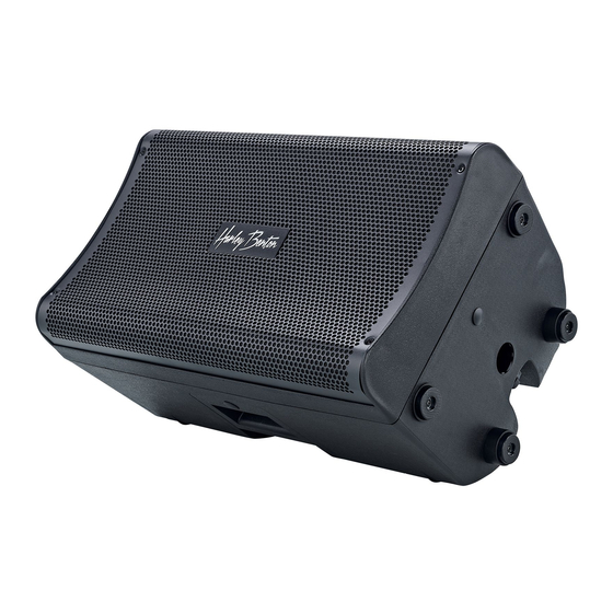
Features Features The device is characterized by the following features: Full range flat-response case for a modern digital guitar setup (amp modelling and multi- effects processor) 4 DSP sound programmes various DSP equalizer modes, each with ±12 dB level control per band 1200 watt power amp, class D 12-inch woofer and 1-inch tweeter suitable for use as floor monitor or on a tripod... -
Page 13: Starting Up
Starting up Starting up Unpack and check carefully there is no transportation damage before using the unit. Keep the equipment packaging. To fully protect the product against vibration, dust and moisture during transportation or storage use the original packaging or your own packaging material suitable for transport or storage, respectively. - Page 14 Starting up NOTICE! Use of stands When mounting the device onto a stand, ensure that the stand is in a safe and stable position and that the weight of the device does not exceed the maximum permissible load capacity of the stand. The unit can be mounted on a tripod or set up on the floor or a sufficiently sized and stable surface.
-
Page 15: Connections And Controls
Connections and controls Connections and controls FRFR-112A Guitar DSP... - Page 16 Connections and controls Front panel [DSP] backlit display for DSP functions [MASTER / PUSH FOR DSP] Rotary control for the overall volume, push button for activating the DSP functions [INPUT 1 LINE] Rotary gain control for input 1. Turning clockwise increases the input gain for connecting microphones. Turning counterclockwise decreases the input gain for connecting instruments or devices with line level outputs.
- Page 17 Connections and controls Front panel [OUTPUT] Line output, designed as XLR chassis plug. The combined signal of both inputs is present here, unaffected by DSP. [AUX IN] 3.5 mm phone socket for connecting line level devices such as MP3 or CD players. Stereo signals are combined. Rear panel IEC chassis plug with fuse holder for the power supply LED [ON OFF].
-
Page 18: Dsp Functions
DSP functions DSP functions Function selection Press [MASTER | PUSH FOR DSP] to call up the main menu. Turn [MASTER | PUSH FOR DSP] to switch between menu items or values. Press [MASTER | PUSH FOR DSP] to activate the menu shown in the display or to confirm a value. - Page 19 DSP functions EQ setting Press [MASTER | PUSH FOR DSP] to call up the main menu. Turn [MASTER | PUSH FOR DSP] until the display shows ‘EQ SET’ and press [MASTER | PUSH FOR DSP] to confirm. Turn [MASTER | PUSH FOR DSP] until the display shows ‘EQ TYPE’ and press [MASTER | PUSH FOR DSP] to confirm.
- Page 20 DSP functions Turn [MASTER | PUSH FOR DSP] to raise or lower the level of the selected frequency band and press [MASTER | PUSH FOR DSP] to confirm. Setting the LED mode Press [MASTER | PUSH FOR DSP] to call up the main menu. Turn [MASTER | PUSH FOR DSP] until the display shows ‘LED MODE’...
- Page 21 DSP functions Setting the display brightness Press [MASTER | PUSH FOR DSP] to call up the main menu. Turn [MASTER | PUSH FOR DSP] until the display shows ‘BRIGHT’ and press [MASTER | PUSH FOR DSP] to confirm. Turn [MASTER | PUSH FOR DSP] to set a value between ‘1’ (low) and ‘10’ (high) and press [MASTER | PUSH FOR DSP] to confirm.
- Page 22 DSP functions Reset Press [MASTER | PUSH FOR DSP] to call up the main menu. Turn [MASTER | PUSH FOR DSP] until the display shows ‘RESET’ and press [MASTER | PUSH FOR DSP] to confirm. Turn [MASTER | PUSH FOR DSP] until the display shows ‘Confirm Reset: YES’ and press [MASTER | PUSH FOR DSP] to confirm.
-
Page 23: Technical Specifications
Technical specifications Technical specifications Speaker 12-inch woofer 1" tweeter Amp class Class-D power amp Input connections Mic / Line 2 × XLR / jack combo socket, balanced Line level player 1 × 3.5 mm jack socket Voltage supply IEC chassis plug C14 Output connections Line level mix from both inputs 1 ×... - Page 24 Technical specifications Operating supply voltage 230 V 50 Hz Fuse 5 mm × 20 mm, 3 A, 250 V, slow-blow Dimensions (W × H × D) 348 mm × 607 mm × 355 mm Weight 14.6 kg Ambient conditions Temperature range 0 °C…40 °C Relative humidity 50 %, non-condensing...
-
Page 25: Plug And Connection Assignment
Plug and connection assignment Plug and connection assignment Introduction This chapter will help you select the right cables and plugs to connect your valuable equip‐ ment in such a way that a perfect sound experience is ensured. Please note these advices, because especially in ‘Sound & Light’ caution is indicated: Even if a plug fits into the socket, an incorrect connection may result in a destroyed power amp, a short circuit or ‘just’... - Page 26 Plug and connection assignment Since the interference affects both cores equally, by subtracting the phase-shifted signals, the interfering signal is completely neutralized. The result is a pure signal without any noise inter‐ ference. 1/4" TS phone plug (mono, unbalanced) Signal Ground, shielding 1/4"...
- Page 27 Plug and connection assignment XLR plug (balanced) Ground, shielding Signal (in phase, +) Signal (out of phase, –) Shielding on plug housing (option) XLR plug (unbalanced) Ground, shielding Signal Bridged to pin 1 FRFR-112A Guitar DSP...
-
Page 28: Cleaning
Cleaning Cleaning Device components Clean the device components that are accessible from the outside regularly. The cleaning fre‐ quency depends on the operating environment: damp, smoky or particularly dirty environ‐ ments can cause greater accumulation of dirt on the device components. Clean with a dry soft cloth. -
Page 29: Protecting The Environment
Protecting the environment Protecting the environment Disposal of the packaging mate‐ rial For the transport and protective packaging, environmentally friendly materials have been chosen that can be supplied to normal recycling. Ensure that plastic bags, packaging, etc. are properly disposed of. Do not just dispose of these materials with your normal household waste, but make sure that they are collected for recycling. - Page 30 Notes guitar combo...
- Page 32 Musikhaus Thomann · Hans-Thomann-Straße 1 · 96138 Burgebrach · Germany · www.thomann.de...
Need help?
Do you have a question about the Harley Benton FRFR-112A Guitar DSP and is the answer not in the manual?
Questions and answers