Table of Contents
Advertisement
Quick Links
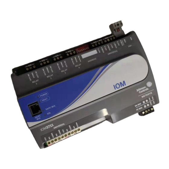
IOM3711 Input/Output Module Installation Instructions
MS-IOM3711-0U
Application
The IOM37 input/output expansion module is a part of
the Metasys® system Field Equipment Controller family.
Input/Output Module (IOM) expansion modules expand
the number of points connected to a Network Automation
Engine (NAE), Network Control Engine (NCE), Field
Equipment Controller (FEC), VAV Modular Assembly
(VMA), or Advanced Application Field Equipment
Controller (FAC) to monitor and control a wide variety of
HVAC equipment.
IOM expansion modules operate on an RS-485 BACnet®
MS/TP Bus and integrate into Johnson Controls® and
third-party BACnet systems.
Note: At CCT Release 10.3 and Release Module (RM)
10.2, a new capability allows VMAs, FECs, and
FACs to communicate by using either the BACnet
or the N2 field bus networking protocol. The
operation of the Input/Output Module (IOM) is not
affected by the selection of the BACnet or the N2
protocol in the host controller, when the (IOM) is
connected to the host controller using the SA bus.
Only the BACnet protocol is supported when the
(IOM) is connected directly to the trunk using the
FC bus.
Important: The MS-IOM3711-0U model is used in
Metasys Release 8.1 smoke control
applications and is UL 864 UUKL/UUKLC
10th Edition Smoke Control Listed. You
must refer to the Metasys® System UL 864
10th Edition UUKL/ORD-C100-13 UUKLC
Smoke Control System Technical Bulletin
(LIT-12012487) for detailed requirements
and procedures for installing,
commissioning, and operating UL 864
UUKL/UUKLC Listed Metasys system
devices. The UL 864 UUKL/UUKLC listing
for Smoke Control Equipment is voided if
(1) you do not use the required software
tools at the required versions; or (2) you do
not meet the requirements or do not follow
the procedures as documented in the
Metasys® System UL 864 10th Edition
UUKL/ORD-C100-13 UUKLC Smoke
Control System Technical Bulletin
(LIT-12012487).
IOM3711 Input/Output Module Installation Instructions
Part No. 24-10144-238, Rev. A
North American Emissions
Compliance
Canada
This Class (A) digital apparatus meets all the
requirements of the Canadian Interference-Causing
Equipment Regulations.
Cet appareil numérique de la Classe (A) respecte toutes
les exigences du Règlement sur le matériel brouilleur
du Canada.
United States
This equipment has been tested and found to comply
with the limits for a Class A digital device pursuant to
Part 15 of the FCC Rules. These limits are designed to
provide reasonable protection against harmful
interference when this equipment is operated in a
commercial environment. This equipment generates,
uses, and can radiate radio frequency energy and, if not
installed and used in accordance with the instruction
manual, may cause harmful interference to radio
communications. Operation of this equipment in a
residential area may cause harmful interference, in which
case the users will be required to correct the interference
at their own expense.
Installation
Observe these guidelines when installing an expansion
module:
•
Transport the expansion module in the original
container to minimize vibration and shock damage.
•
Verify that all parts shipped with the expansion
module.
•
Do not drop the expansion module or subject it to
physical shock.
Parts Included
•
one controller with removable terminal blocks (Power
and SA/FC bus are removable)
•
one installation instructions sheet
Software Release 8.1
Issued March 2018
1
Advertisement
Table of Contents

Related Manuals for Johnson Controls IOM3711


Summary of Contents for Johnson Controls IOM3711
- Page 1 Cet appareil numérique de la Classe (A) respecte toutes IOM expansion modules operate on an RS-485 BACnet® les exigences du Règlement sur le matériel brouilleur MS/TP Bus and integrate into Johnson Controls® and du Canada. third-party BACnet systems. Note: At CCT Release 10.3 and Release Module (RM) United States 10.2, a new capability allows VMAs, FECs, and...
-
Page 2: Materials And Special Tools Needed
1. Or hold the expansion • Do not install the expansion module in an airtight module up to the wall or surface in a proper mount enclosure. position and mark the hole locations through the mounting clips. IOM3711 Input/Output Module Installation Instructions... - Page 3 (or anchors). Carefully tighten all of the screws. Important: Do not overtighten the mounting screws. Overtightening the screws may damage the mounting clips. Figure 3: IOM3711 Physical Features Table 1: IOM3711 Physical Features Callout Physical Feature: Description and References Relay Output Terminal Blocks. (See...
-
Page 4: Terminal Blocks And Bus Ports
Table 1: IOM3711 Physical Features Callout Physical Feature: Description and References Cover Lift Tab (See Removing the Expansion Module Cover) Sensor Actuator (SA) Bus or Field Controller (FC) Bus Terminal Block. (See Table Universal Inputs (UI) Terminal Blocks. (See Table Light-Emitting Diode (LED) Status Indicators. -
Page 5: Supply Power Terminal Block
(daisy chain) the 15 VDC power leads on the SA bus (Figure 5) or the cable shields on the FC bus (Figure 4). The SA bus supervisor supplies 15 VDC to devices on the SA bus requiring power. IOM3711 Input/Output Module Installation Instructions... -
Page 6: Wireless Network Applications
UUKL/UUKLC Listed Metasys system devices. Termination Details A set of Johnson Controls® termination diagrams provides details for wiring inputs and outputs to the controllers. See the figures in this section for the applicable termination diagrams. Table 2: Termination Details Type of Field Device... - Page 7 Input/Output Voltage Input - Internal Source Voltage Input (Self-Powered) Current Input - External Source (Isolated) Current Input - Internal Source (2-wire) Current Input - Internal Source (3 wire) Current Input - External Source (in Loop) IOM3711 Input/Output Module Installation Instructions...
- Page 8 24 VAC Binary Output UO or RO (Switch Low, External Source) 24 VAC Binary Output UO or RO (Switch High, External Source 0–10 VDC Output to Actuator (External Source) 0–10 VDC Output to Actuator (Internal Source) IOM3711 Input/Output Module Installation Instructions...
- Page 9 Type of Termination Diagrams Input/Output Incremental Control to Actuator(Switch Low, Externally Sourced) Incremental control to Actuator (Switch High, Externally Sourced) Voltage (Analog Output) 4–20 mA Output to Actuator Analog Output (Current) 4–20 mA Output to Actuator IOM3711 Input/Output Module Installation Instructions...
-
Page 10: Terminal Wiring Guidelines, Functions, Ratings, And Requirements
Table Internal 12 V. 15k ohm pull up Qualified Sensors: 0-2k ohm potentiometer, RTD (1k Nickel [Johnson Controls® sensor], 1k Platinum, and A99B Silicon Temperature Sensor) Negative Temperature Coefficient (NTC) Sensor (10k Type L, 10k JCI Type II, 2.252k Type... - Page 11 1/4 hp 120 VAC, 1/2 hp 240 VAC 360 VA Pilot Duty at 120/240 VAC (B300) 3 A Non-inductive 24–240 VAC CE Marking (-2 model only): 6 (4) A N.O. or N.C. only, 240 VAC IOM3711 Input/Output Module Installation Instructions...
- Page 12 30 V AC/DC maximum output voltage 0.5 A maximum output current 40 mA minimum load current (hold current) OCOMn Universal Output (UO) Common Same as OUT Isolated from all other terminal commons, including other UO commons. IOM3711 Input/Output Module Installation Instructions...
-
Page 13: Cable And Wire Length Guidelines
(in mA) when wiring inputs and outputs. Figure 8: Maximum Wire Length for Low-Voltage (<30 V) Inputs and Outputs by Current and Wire Size IOM3711 Input/Output Module Installation Instructions... -
Page 14: Sa/Fc Bus And Supply Power Wiring Guidelines
The SA Bus and FC Bus wiring recommendations in this table are for MS/TP bus communications at 38,400 baud. For more information, refer to the MS/TP Communications Bus Technical Bulletin (LIT-12011034). IOM3711 Input/Output Module Installation Instructions... -
Page 15: Setup And Adjustments
21, set switch 16 to ON first, then set switch 4 ON, followed by switch 1 (16+4+1= 21). See Figure 3. Set switch 128 to OFF to enable the hard-wired SA and FC bus application. IOM3711 Input/Output Module Installation Instructions... - Page 16 2. Pivot the top of the cover further to release it from the the FC bus, set the EOL switch to ON. If the lower two latches. expansion module is not a terminating device on the bus, set the EOL switch to Off. IOM3711 Input/Output Module Installation Instructions...
-
Page 17: Repair Information
Repair Information The MS-IOM3710-0U and MS-IOM3711-0U models are UL 864 10th Edition UUKL/ORD-C100-13 UUKLC listed for smoke control. If a expansion module fails to operate within its specifications, contact the Johnson Controls Repair Center in Louisville, Kentucky, at 1-502-671-7312. Accessories Table 1 for controller accessories ordering information. -
Page 18: Technical Specifications
150 x 190 x 53 mm (5-7/8 x 7-1/2 x 2-1/8 in.) including terminals and mounting clips Depth) Note: Mounting space requires an additional 50 mm (2 in.) space on top, bottom and front face of expansion module for easy cover removal, ventilation and wire terminations. Weight 0.5 kg (1.1 lb) IOM3711 Input/Output Module Installation Instructions... - Page 19 The performance specifications are nominal and conform to acceptable industry standard. For application at conditions beyond these specifications, consult the local Johnson Controls® office. Johnson Controls shall not be liable for damages resulting from misapplication or misuse of its products.
Need help?
Do you have a question about the IOM3711 and is the answer not in the manual?
Questions and answers