Hoymiles MI-300 User Manual
Microinverter
Hide thumbs
Also See for MI-300:
- Quick installation manual (2 pages) ,
- User manual (28 pages) ,
- Installation training (24 pages)
Table of Contents
Advertisement
Quick Links
Advertisement
Table of Contents
Troubleshooting

Related Manuals for Hoymiles MI-300


Summary of Contents for Hoymiles MI-300
- Page 1 Version 2.0 (June 2020)
- Page 2 About the Manual This manual contains important instructions for the MI-300/MI-350/MI-400 Microinverter and must be read in its entirety before installing or commissioning the equipment. For safety, only qualified technician, who has received training or has demonstrated skills can install and maintain this Microinverter under the guide of this document.
-
Page 3: Table Of Contents
6.3 On-site Inspection (For qualified installer only) ..................21 6.4 Routine Maintenance ..........................22 6.5 Replace Microinverter ..........................22 7. Decommissions ..............................23 7.1 Decommissions ............................23 7.2 Storage and Transportation ........................24 © 2019 Hoymiles Converter Technology Co., Ltd. All rights reserved. - Page 4 WIRING DIAGRAM – 230VAC SINGLE PHASE: ..................28 WIRING DIAGRAM – 230VAC / 400VAC THREE PHASE: ............... 29 WIRING DIAGRAM –120VAC / 240VAC SPLIT PHASE: ................30 WIRING DIAGRAM – 120VAC / 208VAC THREE PHASE: ............... 31 © 2019 Hoymiles Converter Technology Co., Ltd. All rights reserved.
-
Page 5: Important Notes
2. About Safety 2.1 Important Safety Instructions The MI-300/MI-350/MI-400 Microinverter is designed and tested according to international safety requirements. However, certain safety precautions must be taken when installing and operating this © 2019 Hoymiles Converter Technology Co., Ltd. All rights reserved. -
Page 6: Explanation Of Symbols
➢ Do not use the equipment if any operating anomalies are found. Avoid temporary repairs. ➢ All repairs should be carried out using only qualified spare parts, which must be installed in accordance with their intended use and by a licensed contractor or authorized Hoymiles service representative. -
Page 7: Radio Interference Statement
4) Contact your dealer or an experienced radio/TV technician for help. 3. About Product 3.1 About Single Unit “The world’s First Daisy-Chain Single Unit Microinverter” with extremely wide DC input operating voltage range (16-60V) and low start-up voltage (22V only). © 2019 Hoymiles Converter Technology Co., Ltd. All rights reserved. -
Page 8: Highlights
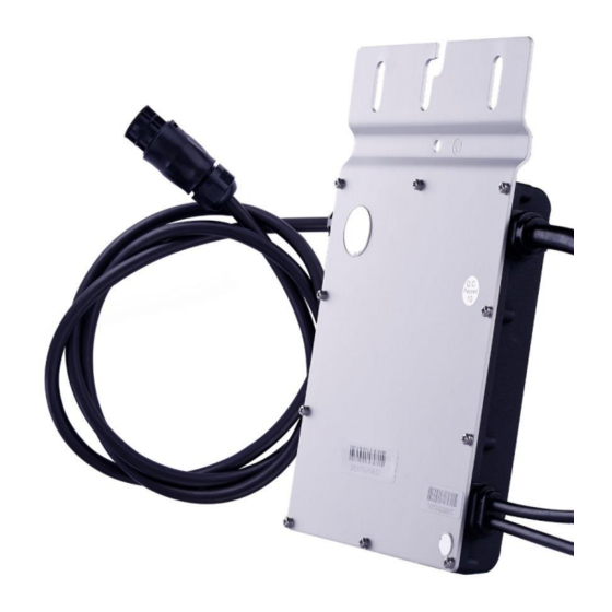
MI-300/MI-350/MI-400 Hoymiles Single unit Microinverter MI-300/MI-350/MI-400 is the perfect selection for PV system with uneven number of panels with world’s NO.1 CEC weighted efficiency – 96.50% (peak efficiency 96.70%) in 2015. 3.2 Highlights Maximum output power up to 300W/350W/400W; Adapted to 60 & 72 cells PV panels. -
Page 9: About Function
*Note: All accessories above are not included in the package, and need to be purchased separately. Please contact our sales representative for the price. (M8 screws need to be prepared by installer-self.) © 2019 Hoymiles Converter Technology Co., Ltd. All rights reserved. -
Page 10: Installation Precaution
5.3 Space Distance Required Please install the Microinverter at least 50cm above the ground/roof for better communication with Hoymiles DTU. Please contact with Hoymiles technical engineer if there is any special circumstance. 5.4 Preparation Installation of the equipment is carried out based on the system design and the place in which the equipment is installed. -
Page 11: Installation Steps
A) Mark the approximate center of each panel on the frame. B) Fix the screw on the rail. C) Hang the microinverter on the screw (shown as picture below), and tighten the screw. The silver © 2019 Hoymiles Converter Technology Co., Ltd. All rights reserved. - Page 12 B) Install the AC end cap on the open AC connector of the last microinverter in the AC branch circuit. Step 3. Connect AC End Cable Make the end cable 1. Take the AC port apart into 3 parts: © 2019 Hoymiles Converter Technology Co., Ltd. All rights reserved.
- Page 13 Connect the AC end cable to the AC male connector of the first Microinverter to complete the circuit. C) Connect the other side of the AC end cable to the distribution box, and wire it to the local grid network. © 2019 Hoymiles Converter Technology Co., Ltd. All rights reserved.
- Page 14 Affix the serial number label to the respective location on the installation map. Step 5. Connect PV Modules Mount the PV modules above the microinverter. B) Connect the PV modules’ DC cables to the DC input side of the microinverter. © 2019 Hoymiles Converter Technology Co., Ltd. All rights reserved.
-
Page 15: Troubleshooting
6.3. If you use the microinverter of serial number “1020xxxxxxxx” and “1021xxxxxxxx”, please refer to chapter 6.2 and chapter 6.4. *Note: The microinverter of serial number “1062xxxxxxxx” can only work with the new Hoymiles gateway, DTU-Pro (SN: 10F7xxxxxxxx, 10F8xxxxxxxx), DTU-G100 (SN: 10D2xxxxxxxx) and DTU-W100 (SN: 10D3xxxxxxxx). - Page 16 MI-300/MI-350/MI-400 1.Check if the grid configuration parameter is correct and upgrade again. Grid configuration 2. If the fault still exists, contact your dealer or Hoymiles technical parameter error support. 1. If the alarm occurs accidentally and the microinverter can still work normally, no special treatment is required.
- Page 17 2. If the alarm occurs frequently, check whether the grid frequency change rate change rate is within the acceptable range. If no, contact the local power operator or change the grid frequency change rate limit via Hoymiles monitoring system with the consent of the local power operator. Power grid outage Please check whether there is a power grid outage.
-
Page 18: Troubleshooting List (Sn: 1020Xxxxxxxx, 1021Xxxxxxxx)
2. If the alarm occurs frequently and cannot be recovered, contact your dealer or Hoymiles technical support. 6.2 Troubleshooting List (SN: 1020xxxxxxxx, 1021xxxxxxxx) Alarm Alarm Name Suggestion Code 1.Please make sure that the microinverter works normally. Offline © 2019 Hoymiles Converter Technology Co., Ltd. All rights reserved. - Page 19 If no, contact the local power operator or change the grid overfrequency or underfrequency protection limit via Hoymiles monitoring system with the consent of the local power operator. 1. If the alarm occurs accidentally, the grid voltage may be abnormal temporarily.
-
Page 20: Status Led Indicator (Sn: 1022Xxxxxxxx)
DTU and microinverter. Then try 5200 Firmware error again. 3. If the fault still exists, contact your dealer or Hoymiles technical support. Please check if the microinverter is turned off by the zero export mode, 8310 Shut down otherwise please contact your dealer. -
Page 21: Status Led Indicator (Sn: 1020Xxxxxxxx, 1021Xxxxxxxx)
✓ Flashing Red and Green alternately: Firmware is corrupted. *Note: All the faults are reported to the DTU, refer to the local APP of the DTU or Hoymiles Monitoring Platform for more information. 6.4 Status LED Indicator (SN: 1020xxxxxxxx, 1021xxxxxxxx) The LED flashes six times at start up. -
Page 22: Routine Maintenance
Avoid temporary repairs. All repairs should be carried out using only genuine spare parts. If all the microinverters connect to the DTU-Pro, the DTU can limit the output power imbalance of all the microinverters between phases to below 3.68kW if required. Please refer to “Hoymiles Technical Note Limit Phase Balance” for more details. -
Page 23: Decommissions
“More” on the right side of the page, and select “Replace”. Input the new Microinverter’s SN and click “Ok” to complete the station changes. 7. Decommissions 7.1 Decommissions Disconnect the inverter from DC input and AC output; remove all connection cable from the © 2019 Hoymiles Converter Technology Co., Ltd. All rights reserved. -
Page 24: Storage And Transportation
7.2 Storage and Transportation Hoymiles packages and protects individual components using suitable means to make the transport and subsequent handling easier. Transportation of the equipment, especially by road, must be carried out by suitable ways for protecting the components (in particular, the electronic components) from violent, shocks, humidity, vibration, etc. -
Page 25: Dc Input
MI-300/MI-350/MI-400 DC short circuit current. The output DC power of PV module is NOT recommended to exceed 1.35 times the output AC power of the microinverter. Refer to “Hoymiles Warranty Terms & Conditions” for more informatio 8.1 DC Input Model... -
Page 26: Mechanical Data
12 years standard, 25 years optional IEC61727, IEC62116, IEC61683, VFR2019, Compliance VDE0126-1-1, IEC/EN 62109-1/-2, IEC/EN 61000-3- 2/-3, IEC/EN-61000-6-1/-2/-3/-4 *Note: Voltage and frequency ranges can be extended beyond nominal if required by the utility. © 2019 Hoymiles Converter Technology Co., Ltd. All rights reserved. -
Page 27: Installation Map
MI-300/MI-350/MI-400 Appendix 1: Installation Map © 2019 Hoymiles Converter Technology Co., Ltd. All rights reserved. -
Page 28: Wiring Diagram - 230Vac Single Phase
MI-300/MI-350/MI-400 Appendix 2: WIRING DIAGRAM – 230VAC SINGLE PHASE: © 2019 Hoymiles Converter Technology Co., Ltd. All rights reserved. -
Page 29: Wiring Diagram - 230Vac / 400Vac Three Phase
MI-300/MI-350/MI-400 WIRING DIAGRAM – 230VAC / 400VAC THREE PHASE: © 2019 Hoymiles Converter Technology Co., Ltd. All rights reserved. -
Page 30: Wiring Diagram -120Vac / 240Vac Split Phase
MI-300/MI-350/MI-400 WIRING DIAGRAM –120VAC / 240VAC SPLIT PHASE: © 2019 Hoymiles Converter Technology Co., Ltd. All rights reserved. -
Page 31: Wiring Diagram - 120Vac / 208Vac Three Phase
MI-300/MI-350/MI-400 WIRING DIAGRAM – 120VAC / 208VAC THREE PHASE: © 2019 Hoymiles Converter Technology Co., Ltd. All rights reserved.
Need help?
Do you have a question about the MI-300 and is the answer not in the manual?
Questions and answers