Cognex DataMan 300 Series Quick Reference Manual
Id readers
Hide thumbs
Also See for DataMan 300 Series:
- Quick reference manual (44 pages) ,
- Manual (17 pages) ,
- Installation manual (8 pages)
Table of Contents
Advertisement
Quick Links
Advertisement
Table of Contents

Related Manuals for Cognex DataMan 300 Series


Summary of Contents for Cognex DataMan 300 Series
- Page 1 COGNEX ® DataMan 300 Series ® Quick Reference Guide...
-
Page 2: Setting Up Your Dataman
About DataMan 300 Series • For More Information • Getting Started Section Title Page 4 Page 2 • DataMan 300 Series Accessories • DataMan 300 Systems Reader Layout • Installing the Lens • Installing a Filter • Setting Up Your DataMan Page 10 Installing a Filter in a Flat LED Front Cover •... - Page 3 DataMan Questions and Answers provides context-sensitive DataMan 300 series readers are packaged in a rugged, IP65-rated housing, information. You can view this help inside the Setup Tool or as and they provide numerous ease-of-use features, including one button to a stand-alone help file.
- Page 4 DataMan 300 Series Accessories M12/S-MOUNT LENS OPTIONS EXTERNAL LIGHTS (RED LED) 10.3 mm M12 lens with locking (DM300-LENS-10) Ring light (CLRR-R7030G1CLR) 10.3 mm IR M12 lens with locking Back light (CLRB-F100100G1) (DM300-LENS-10-IR) Coaxial (DOAL) light (CLRO-K5050G1) Liquid lens module and pre-focused 10.3 mm...
- Page 5 DataMan 300 Series Accessories (Continued) DataMan 300 Systems POWER SUPPLIES 2DMax+™ 1DMax+™ IDQuick™ — for Omni- — Best- — High- hard 24V power supply (ACC-24l) directional In-Class Speed to read Resolution 1-D Code 24V power supply (PS-KIT-1) DPM and Reading...
-
Page 6: Reader Layout
Reader Layout Network Peak meter The following image shows the built-in lighting system of the DataMan 300 Error series reader, underneath the plastic lighting cover. Good/ NOTE: The image below shows the two different front covers: the cover with front- bad read mounted filter and the flat cover with an internal filter. -
Page 7: Installing The Lens
C-Mount lens options to be installed on your While carefully avoiding rotating the lens, press the rubber lens cone DataMan 300 series reader. into the reader until it snaps into place around the nose of the lens. - Page 8 Installing the Lens (Continued) Insert and tighten screws. Tighten the lens. After fixing the lens, verify focus position again, using the steps above. Attach front cover. PHILLIPS PAN HEAD M2 X 6MM Tighten in sequence. Torque limit: 9 Ncm (0.08 in-lbs).
-
Page 9: Installing A Liquid Lens
Installing the Lens (Continued) Installing a Liquid Lens Connect the liquid lens cable to the reader. Remove the lens plug as described in Step 1 on page 12 above. Thread the lens into the reader. Snap the liquid lens module onto the nose of the lens, making sure that it lies flat. - Page 10 Installing the Lens (Continued) Attach front cover. Place the reader at the desired working distance from focus target. Light connector 1. Connect the reader to the Setup Tool. 2. On the Results Display pane, check the Focus Feedback option and enable Live Display.
- Page 11 Installing the Lens (Continued) Installing a C-Mount Lens Remove the lens plug as described in Step 1 on page 12 above. Thread the lens into the reader. Attach C-Mount cover base. Place the reader at the desired working distance from focus target. 1.
- Page 12 Installing the Lens (Continued) Add screws to C-mount cover base. Attach front cover. NOTE Do not unscrew the front-most part of the nose of the cover to avoid risking the glass lens falling out. Tighten in sequence. Torque limit: 9 Ncm (0.8 in-lbs).
- Page 13 Installing a Filter (Old-Style Cover) You can replace the window glass disk which is part of the light cover of your 3. Remove clip and remove the glass disk. DataMan 300 reader with an optical filter. Observe the following constraints on the filter: •...
- Page 14 Installing a Filter (Flat-Front Cover) 3. Working from the front of the PCB, press the legs of the filter holder Perform the following steps to install an optical filter in the front cover. gently together and pull off the clip. Observe the following constraints on the filter: Filter retaining clip •...
- Page 15 Installing a Filter (Flat-Front Cover - Continued) 5. Snap fit the filter retaining clip onto the legs of the filter holder. 6. Insert the PCB with the filter retaining clip and the filter holder back Ensure that the laser modules slide into the laser guides and the orientation into the front cover.
- Page 16 Installing a Filter (Flat-Front Cover - Continued) 8. Remount the front cover. 7. Insert the rubber seal. Observing the tightening sequence below, tighten all four screws to 9 Ncm using a torque wrench. Rubber seal Left Right PHILLIPS PAN HEAD M2 X 6MM Tighten in Note that the seal can only be installed in the correct orientation.
-
Page 17: External Light Mounting Brackets
External Light Mounting Brackets Choose one of the following light options: You can mount your reader using external light mounting brackets. The brackets are intended to mount any of the different lights to the reader. They can also be used to mount the reader (with lights attached) to •... -
Page 18: Setting Focus
Setting Focus For setting Focus Sweep, follow these guidelines: There is a range of reading distances available for different code sizes and focus positions. To set focus on your reader, use the following options • If your application has a consistent reading range, set the focus depending on whether you use a liquid lens or a manual focus lens. -
Page 19: Field Of View And Reading Distances
Field of View and Reading Distances Setting Focus (Continued) The following maps show the field of view of the DataMan 300 series target does not completely fill the image, make sure that there are no high- contrast features visible outside of the target (see previous bullet). - Page 20 Reading Distance and Field of View (DataMan 300 Series Readers with a 10.3 mm Lens) This map shows the field of view of the DataMan 300 series readers with a 10.3 mm 396 mm (15.5 in) 243.4 mm (9.5 in) lens (with or without a liquid lens).
- Page 21 Reading Distance and Field of View (DataMan 300 Series Readers with a 16 mm Lens) This map shows the field of view of the DataMan 300 series readers with a 16 mm lens. The FOV values are shown as follows: 241.9 mm (9.
- Page 22 Reading Distance and Field of View (DataMan 300 Series Readers with a 19 mm Liquid Lens) This map shows the field of view of the DataMan 300 series readers with a 19 mm liquid lens. The FOV values are shown as follows: •...
- Page 23 Reading Distance and Field of View (DataMan 300 Series Readers with a 25 mm Lens) This map shows the field of view of the DataMan 300 series readers with a 25 mm lens. The FOV values are shown as follows: •...
- Page 24 Dimensions Observe the following DataMan 300 series reader dimensions when installing S-Mount (M12) Lens version your reader. M3-5 (4x) mounting holes for the device operating buttons LEDs C-Mount Lens version M3-6 (4x) mounting holes for external illumination 46 DataMan 300 Quick Reference Guide...
-
Page 25: Dataman 300 Series Imager Specifications
DataMan 303: 1600 x 1200 Electronic Shutter Speed • minimum exposure: 5 µs (DataMan 300 and 302), 12 µs 3. Connect the DataMan 300 Series reader to your PC. (DataMan 303) 4. Launch the Setup Tool and click Refresh. •... -
Page 26: Results Display
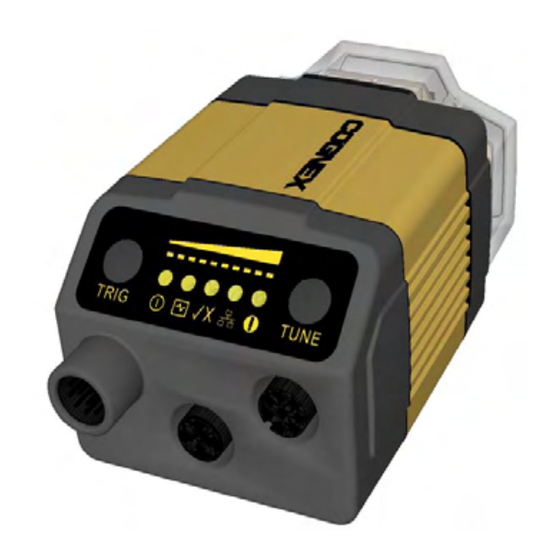
Start the Setup Tool Trigger Tune Connect the reader to the Setup Tool to configure it with Latest image Context based help Region of interest button button button the type of symbologies it will decode as well as other parameters, such as the type of trigger it will use and the format of the results it will generate. -
Page 27: Troubleshooting An Ethernet Connection
IP address, use the Force Network Settings options. Either A reader can also generate a Cognex device configuration (.cdc) file, method should allow the DataMan 300 series reader to appear in the list of which stores the set of runtime parameters plus any identification... - Page 28 Load a saved device configuration .cdc file, with run-time parameters plus device-specific Use the System menu to manage the current settings on the reader information for a particular DataMan 300 series and to upgrade the features it currently supports: reader.
-
Page 29: Industrial Protocols
Test Mode Test mode lets you configure and test a reader that is connected to a The DataMan 300 series readers support the following industrial protocols: production line without needing to slow down or stop your line. To enter • EtherNet/IP™... -
Page 30: External Triggers
External Triggers If you are using external triggering you can use any of these methods to DataMan 300 series readers support the following trigger modes: trigger your DataMan 300 series reader: • Self: At an interval you configure, the reader automatically detects and decodes codes in its field of view. -
Page 31: Multi-Reader Triggering
It is possible to configure a variety of acquisition parameters for your multi-reader triggering, also known as master-slave configuration. In this DataMan 300 series reader on a unified Read Setups pane. configuration, you configure multiple DataMan readers as a group. Whenever... - Page 32 You can define a stack of filters to be applied to each image acquired settings for the given reading situation, based on parameters of illumination, by your DataMan 300 series reader. You can select the following filters camera and decoder properties, and focal distance. Tuning autodisciminates all on the Setup Tool’s Image Filtering pane (under Light and Imager...
- Page 33 DataMan 300 Series Image Filtering (Continued) • Close This filter performs a dilation followed by an erosion to filter out dark features that are smaller than the size of the processing neighborhood. The result is an output image with slightly increased overall brightness.
-
Page 34: Training The Reader
DataMan 300 Series Image Filtering (Continued) Training the Reader 5. Go to the Displayed Image Settings pane and change the Images to Training your reader with the expected symbology can make the time Use according to what you want to see on Live Display: the original or the required to decode successive symbols more consistent. -
Page 35: Training Feedback
Scripting Training the Reader (Continued) Training Feedback In addition to standard formatting possibilities, you have the option to write a script inside the Setup Tool. On the Script-Based Formatting The second LED from left on the reader tab, when script-based formatting is enabled, you can define a glows green to indicate that it is currently JavaScript module to format data according to your needs. -
Page 36: Package Detection Support
External Light Control Package Detection Support You can connect your package detection sensor to one of the digital inputs A 4-pin cable is provided for the external light of your DataMan reader. When the reader receives a signal that a package is control. -
Page 37: Signal Name
I/O Cable (CCB-M12xM12Fy-xx) I/O Cable (CCBL-05-01) The I/O cable provides access to trigger and high-speed The I/O cable provides access to trigger and high- outputs. Unused wires can be clipped short or tied back speed outputs. Unused wires can be clipped short or using a tie made of non-conductive material. -
Page 38: High-Speed Output Lines
High-Speed Output Lines The high-speed outputs can be used as either NPN (pull-down) or PNP (pull-up) For PNP lines, the external load should be connected between the output lines. For NPN lines, the external load should be connected between the output and the negative supply voltage (0V). -
Page 39: High Speed Output Wiring
High Speed Output Wiring To connect the high-speed outputs to a relay, LED or similar load, To connect to an NPN-compatible PLC input, connect Output 0, Output 1, connect the negative side of the load to the output and the positive side Output 2, or Output 3 directly to the PLC input. -
Page 40: Acquisition Triggering
Ethernet M12 to RJ45 Cable Acquisition Triggering The Ethernet cable provides Ethernet connection for network communications. The acquisition trigger input on the reader is opto-isolated. To trigger The Ethernet cable can be connected to a single device or provide connections from an NPN (pull-down) type photo-detector or PLC output, connect to multiple devices via a network switch or router. -
Page 41: Warnings And Notices
Canada ICES-003 • Do not attempt to service or repair this product -- return it to Cognex for service. European EN55022:2006 +A1:2007, Class A • Do not permit anyone other than Cognex Corporation to service, repair, or adjust this... -
Page 42: Canadian Compliance
Natick, MA 01760 For European Community Users Cognex Corporation shall not be liable for use of our product with equipment Cognex complies with Directive 2002/96/EC OF THE EUROPEAN PARLIA- (i.e., power supplies, personal computers, etc.) that is not CE marked and does MENT AND OF THE COUNCIL of 27 January 2003 on waste electrical and not comply with the Low Voltage Directive. -
Page 43: Dataman 300 Series Specifications
DataMan 300 Series Specifications Compliance Statements (Continued) This product has required the extraction and use of natural resources for its Weight 165 g production. It may contain hazardous substances that could impact health and Operating Temperature 0ºC — 45ºC (32ºF — 113ºF) the environment, if not properly disposed. -
Page 44: Reader Programming Codes
Reboot Scanner Factory Defaults Copyright © 2013 Cognex Corporation All Rights Reserved. This document may not be copied in whole or in part, nor transferred to any other media or language, without the written permission of Cognex Corporation. The hardware and portions of the software described in this document may be covered by one or more of the U.S.
Need help?
Do you have a question about the DataMan 300 Series and is the answer not in the manual?
Questions and answers