
Related Manuals for Grundfos AR


Summary of Contents for Grundfos AR
- Page 1 GRUNDFOS INSTRUCTIONS AR control unit Installation and operating instructions, supplement Other languages http://net.grundfos.com/qr/i/91834764...
-
Page 2: Table Of Contents
DMX 221, DMX 226, DMH 25X and Symbols used in this document DMH 28X dosing pumps when used with an AR control unit. The General information AR control unit is considered part of the pump. All Information not... -
Page 3: Connecting Cables And Plugs
3.2 Connecting cables and plugs If there is a large distance between the dosing pump and an AR control unit mounted on the wall, the Note power supply cable and the motor cable can be extended up to 20 metres (cable cross-section: 1 mm 3.3 Enclosure class... -
Page 4: Dimensional Sketches
3.6 Dimensional sketches Nicht im Stillstand verstellen Adjustable only in operstion 100% Nes pas tournen a l`arret AR control unit mounted on a pump terminal box Fig. 2 Manual 1/min Stop Down Menu Start Mode 220-240V 110-120V Motor:siehe Motorentypenschild AR control unit for wall mounting... - Page 5 Nicht im Stillstand verstellen Adjustable only in operstion 100% Nes pas tournen a l`arret AR control unit mounted on a DMX 221 Fig. 4 Manual 1/min Stop Down Mode Menu Start 110-120V 220-240V Nicht im Stillstand verstellen Adjustable only in operstion...
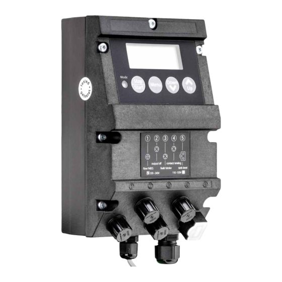
- Page 6 Total approx. 198 gesamt ca. 198 Manual 1/min Stop Down Menu Start Mode output/off contact/analog flow / MBS fault / stroke tank level 220-240V 110-120V AR control unit mounted on a DMH Fig. 6...
-
Page 7: Weight
Stroke control • Permissible air humidity: max. relative humidity: Dosing pumps operated via a AR control unit must be provided 70 % at +40 °C, 90 % at +35 °C. with a Hall sensor. The installation site must be under cover! -
Page 8: Mounting
Current signal control 0-20 mA / 4-20 mA • Connect the control line. Adjustment of stroke frequency proportional to the current signal Weighting of current input 7. Connecting signal lines for AR control unit Inputs and outputs Warning Electrical connections must only be carried out by Inputs... -
Page 9: Connection Diagram For The Ar Control Unit
7.2 Connection diagram for the AR control unit Connection diagram Fig. 7 7.2.1 Diaphragm leakage detection / dosing controller Socket 1 For diaphragm leakage detection (MBS) and/or dosing controller (DC). The diaphragm leakage detection and dosing controller are pre-assembled with an M12 plug for socket 1. - Page 10 7.2.3 Stroke signal / pre-empty signal / error signal Use the stroke signal according to section to control Note 8.10 Creating a master/slave application secondary pumps. Socket 3 Electrically isolated output for stroke signal or pre-empty signal and error signal. Socket 3 Cable Used for...
-
Page 11: Accessories: Cable And Plug For The Ar Control Unit
NO / NO NC / NC Cable assignment of plugs Fig. 9 7.3 Accessories: cable and plug for the AR control unit Description Product number 4-pole M12 plug, suitable for sockets 2 and 4, with 2 m signal cable 96609014 / 321-205... -
Page 12: Using The Pump Electronics
Manual • Service level: for setting the inputs and outputs, thus modifying the version of the AR control unit. It is possible to 1/min revert to the default settings. Saving user settings Stop... - Page 13 8.4.4 Diaphragm leakage detection (MBS) 8.4.6 Remote on/off As an option, the pump can be equipped with a sensor for The pump can be switched off remotely (e.g. from a control diaphragm leakage detection. room). The electronics automatically detects whether a sensor is •...
-
Page 14: Signal Outputs
Setting the dosing controller position 8.5 Signal outputs During the start-up operation, the dosing controller can be set The electronics has the following signal outputs, e.g. in order to according to the operating conditions. return a signal to the control room. 8.5.1 Current signal output To use the control signal output, see section Note... -
Page 15: First Function Level
1. Press the "Menu/Info" button. 8.6 First function level – The first function level is opened and the pump is stopped. 8.6.1 Setting the operating modes 2. Navigate in the first function level by repeatedly pressing the The operating modes are selected in the first function level, and "Menu/Info"... - Page 16 8.6.2 Manual control 8.6.4 Contact signal control with divisor n:1 Dosing with manual on/off and manually adjustable dosing The pump must be started first in this operating flow mode (LED lights up green, "Run" appears in the Note In this operating mode, all the settings are entered on the pump display).
- Page 17 8.6.5 Current signal control 0-20 mA / 4-20 mA For controlling the dosing pump via an external current signal of 0-20 mA (4-20 mA) 0-20mA Analog 1/min Fig. 23 Input signal: 0-20 mA Analog 4-20mA 1/min Fig. 24 Input signal: 4-20 mA •...
-
Page 18: Second Function Level
8.7 Second function level The "Start/Stop" button for stopping the pump is Note active with any code. 8.7.1 Opening / exiting the second function level 1. Press the "Start/Stop" button while the pump is running (LED Open the second function level to set the access code, to enable lights up green). - Page 19 Figure for the second function level Stop Start Menu Keep pressed for 3 seconds Stop Start Code Down Code Stop C:111 Start Menu Dosing controller (not Switch dosing controller on/off Stop Down with all pump types) Start flow ON / OFF Menu Saving of approx.
- Page 20 Current signal control without weighting (default) Current input and current output without weighting [Strokes/min.] max. [mA] min. 0 mA 4 mA 8 mA 12 mA 16 mA 20 mA Fig. 28 Current signal/stroke frequency The assignment between the current signal and stroke frequency is linear by default between 0 and the maximum stroke frequency (depending on pump type) for a current input signal of 0 mA to 20 mA (curve 1) or 4 mA to 20 mA (curve 2).
- Page 21 Current input and current output with weighting [Strokes/min.] max. [mA] min. 0 mA 4 mA 8 mA 12 mA 16 mA 20 mA Fig. 29 Current signal control with weighting Setting the weighting (in the second function level) Stop Menu Start 0-20 mA Analog...
-
Page 22: Service Level
8.8 Service level Open the service level to modify the switch assignments of the electronics. 8.8.1 Modifying the switch assignment You are modifying the default settings of your AR Note control unit. They will therefore differ from the technical data. - Page 23 1. Relay function (stroke/pre-empty signal selection) 6. Relay output, NO/NC (stroke signal/pre-empty signal) "1:OFF" or "1:ON" appears in the display. "6:NO" or "6:NC" appears in the display ("1/min" and empty- signal symbol flash in the display). • Use the "Up" and "Down" buttons to switch between: •...
-
Page 24: Resetting To Default Settings
8.9 Resetting to default settings You can reboot the AR control unit when you connect the power supply. The electronics is then reset to the default settings in the technical data. The pump is disconnected from the power supply. 1. Simultaneously press the "Up" and "Down" buttons and hold them down. - Page 25 Telefax: +852-27858664 Telefax: +47-22 32 21 50 Canada Turkey GRUNDFOS Canada Inc. Hungary Poland GRUNDFOS POMPA San. ve Tic. Ltd. Sti. 2941 Brighton Road GRUNDFOS Hungária Kft. GRUNDFOS Pompy Sp. z o.o. Gebze Organize Sanayi Bölgesi Oakville, Ontario Park u. 8 ul.
- Page 26 91834764 1016 ECM: 1194249 www.grundfos.com...