Table of Contents
Advertisement
Owner's MANUAL
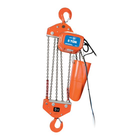
FA Series Electric Chain Hoists - Heavy Duty
®Registered trademark of JET Equipment & Tools Ltd.
www.jetgroupbrands.com
Prod. No. 107202 - 107206
Mod. No. FA1-0.5S - FA-1-5S
Prod. No. 107212 - 107216
Mod. No. FA-0.5S - FA-5S
Prod. No. 107262 - 107266
Mod. No. FA-0.5S - FA-5S
M15-MH107202-66-EN
Advertisement
Table of Contents

Summary of Contents for Jet FA Series
- Page 1 Owner’s MANUAL Prod. No. 107202 - 107206 Mod. No. FA1-0.5S - FA-1-5S FA Series Electric Chain Hoists - Heavy Duty Prod. No. 107212 - 107216 Mod. No. FA-0.5S - FA-5S Prod. No. 107262 - 107266 Mod. No. FA-0.5S - FA-5S ®Registered trademark of JET Equipment &...
- Page 2 TABLE OF CONTENTS Warranty ......................................3 Installation ..................................4 Operation ..................................9 Inspection & Maintenance ............................10 Wiring Diagram ................................15...
- Page 3 This warranty does not cover damage attributable to normal wear and tear. Any JET product that fails during normal use and is within the specified warranty period for that product will be repaired or replaced at JET’S discretion. Repairs and/or replacements are warranted as described for the specific product and only for the remainder of the original warranty period.
- Page 4 The electric chain hoist may not be used in areas where extremely low or high temperatures, high humidity, or chemicals predominate. Consult your local JET distributor when the electric chain hoist is used in a special environment such as HIGH TEMPERATURE (hotter than 104°...
- Page 5 1.2.3. SWINGING OF THE HOIST IN NORMAL CONDITIONS • The body of the hoist is designed to hang right under the hook or trolley and swings towards the load as the load sheave spins. DON’T PREVENT THIS NATURAL SWINGING. (Figure 2) Figure 2 1.2.4.
- Page 6 HOW TO SET UP THE WIRING (3-PHASE 220/440V MODEL) Remove the motor side cover (No. 364). to expose the connector panel with female sockets L1, L2, L3, L4, H1, H2, H3 and H4, and male plugs 1, 2, 3 and 4. (Fig.3) Engage them as specified below, corresponding to the voltage of power supply.
- Page 7 1.3.2. VOLTAGE OF POWER SUPPLY • The voltage of the power supply should be within plus or minus 10% of rated voltage. 1.3.3. SUPPLY CABLE MUST BE THICK ENOUGH • Too large a resistance (in Q) of the cable (or other power supply system) used between the power supply and the hoist will cause the voltage to drop.
- Page 8 KINKED OR TWISTED LOAD CHAIN Kinked load chain should not pass through the chain hoist body. With multi-fall All the welded points of every other links face the same direction models (2~5t rated load models) the load chain sometimes gets twisted by the lower hook turning a somersault between hanging chains.
- Page 9 1.4.2. USE THE CORRECT SIZE BUCKET • If the chain bucket is too small compared with the length of the load chain, the load chain will dangerously overflow from the bucket. Too big a chain bucket tends to be pushed upward by the load. Choose the correct size bucket corresponding to the hoist’s lift by refering to the table below: 2.
- Page 10 2.3. SLINGING 2.3.1. CHECK LIFTING SLINGS • Never use any lifting sling underrated for the load being lifted. Never use any lifting sling inferior in quality or condition. 2.3.2. SAFE AND SURE SLINGINGS Note: The load capacity of the sling should always be rated higher than the load being lifted. Always ensure the sling is not improperly hooked as shown in Fig.12~14.
- Page 11 3.1.3. SWITCH SPRINGS • Ensure switch springs are not damaged or missing NOTE: operation without either one of the springs is dangerous and is prohibited 3.1.4. LOAD CHAIN • Check the load chain for proper lubrication • Check the load chain for any damage, wear, or twisting 3.1.5.
- Page 12 • When assembling 564a and 564b, the same sequence must be followed during reassembly or the brake will not function properly. • Where 2 linings are in use, the notch of one lining must be in the opposite direction to that of the other. 3.2.2.
- Page 13 3.2.3. HOOKS ASSEMBLIES UPPER AND LOWER HOOKS HOOK MOUTH • If the hook has stretched it must be replaced since it has lost the required strength and shock absorbing capability. • Replacement must be made when the dimension A shown in Fig.21 has exceeded the limit shown in the table below. •...
- Page 14 IDLE SHEAVE ROTATION & DEFORMATION (Not applicable to 0.5 Ton model) The idle sheave must be cleaned and checked if there is foreign matter on it. The following three points must be checked: • Abnormalities on the sheave bearings or axis of rotation •...
- Page 20 WARNING: To Avoid Injury 1. DO read ANSI B30.16 safety standard for overhead hoists and hoist manufacturer’s Operating and Maintenance Instructions. 2. DO be familiar with hoist operating controls, procedures and warnings. 3. DO make sure hook travel is in the same direction as shown on controls. 4.


Need help?
Do you have a question about the FA Series and is the answer not in the manual?
Questions and answers