Table of Contents
Advertisement
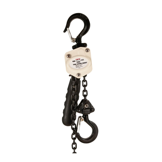
Operating Instructions and Parts Manual
JLP-A Series Manual Lever Hoists/Pullers
1/4- to 6-Ton
JLP-025A
1/4-ton
JET
427 New Sanford Road
LaVergne, Tennessee 37086
Ph.: 800-274-6848
www.jettools.com
(models shown are representative of the series)
1
This .pdf document is bookmarked
JLP-150A
1-1/2-ton
Part No. M-187505
Revision D2 07/2018
Copyright © 2018 JET
Advertisement
Table of Contents


Need help?
Do you have a question about the JLP-025A and is the answer not in the manual?
Questions and answers