Table of Contents
Advertisement
Fresh Solutions, Fit For You
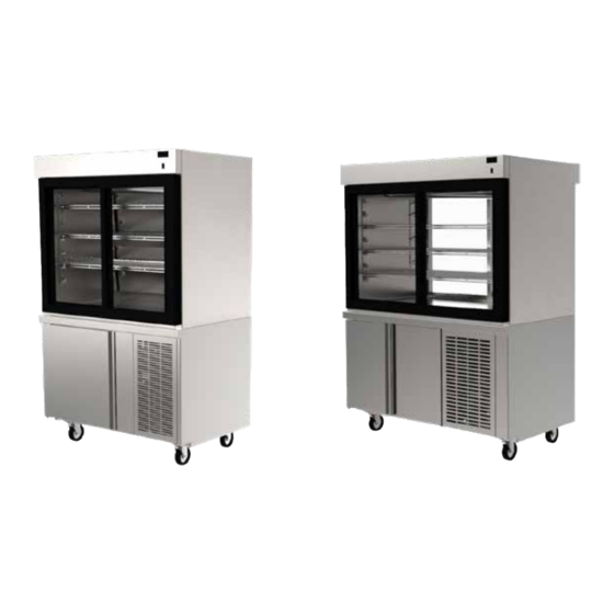
F5 & F15 SERIES
REFRIGERATED DISPLAY CASES
Specifications, Installation, Operation & Maintenance Manual
This manual is updated as new information and models are released.
Visit our website for the latest information.
Caution
,
Read this instruction before operating this equipment.
Original Document
Part Number: 9291460 01/20
Advertisement
Table of Contents

Related Manuals for Delfield F15 Series


Summary of Contents for Delfield F15 Series
- Page 1 Fresh Solutions, Fit For You F5 & F15 SERIES REFRIGERATED DISPLAY CASES Specifications, Installation, Operation & Maintenance Manual This manual is updated as new information and models are released. Visit our website for the latest information. Caution Read this instruction before operating this equipment.
-
Page 2: Table Of Contents
Table of Contents Section 1 General Information Model Numbers ........................4 Serial Number Location ..................... 4 Warranty Information ......................4 Regulatory Certifications ....................4 Section 2 Specifications General Specifications ....................... 5 Electrical Specifications ..................... 6 Voltage ..........................6 Ground Fault Circuit Interrupter ..................6 Rated Amperages, HP, Voltage &... - Page 3 Safety Notices Warning This product contains chemicals known to the State Warning of California to cause cancer and/or birth defects or Read this manual thoroughly before operating, installing other reproductive harm. Operation, installation, and or performing maintenance on the equipment. Failure servicing of this product could expose you to airborne to follow instructions in this manual can cause property particles of glasswool or ceramic fibers, crystalline...
-
Page 4: General Information
Mirrored Back Models Pass-Thru Models near the condensing unit. F5MC36DP F5PC36DP • The serial number on all self-contained F15 series units F5MC48DP F5PC48DP is located behind the compressor housing. F5MC60DP F5PC60DP Always have the serial number of your unit available when calling for parts or service. -
Page 5: Specifications
Section 2 Specifications General Specifications Mirrored F5 - Self-Contained Drop-In Models Models Shelf Area Volume V/Hz/Ph Amps H.P. Nema Plug Ship Weight R290 Charge F5MC36DP 14.1 15.1 115/60/1 5-15P 525lbs / 223kg 150g F5MC48DP 19.6 22.3 115/60/1 5-15P 590lbs / 268kg 150g F5MC60DP 28.4... -
Page 6: Electrical Specifications
Specifications Section 2 Electrical Specifications GROUND FAULT CIRCUIT INTERRUPTER Ground Fault Circuit Interrupter (GFCI/GFI) protection is DANGER a system that shuts down the electric circuit (opens it) Check all wiring connections, including factory when it senses an unexpected loss of power, presumably terminals, before operation. -
Page 7: Refrigeration Specifications
Section 2 Specifications Refrigeration Specifications Model BTU/Hour Capacity Heat of R290 Charge Rejection Base Display Base Display Self-Contained Drop-In F5MC36DP 2576 150g (5.3oz) F5PC36DP 2576 150g (5.3oz) F5MC48DP 2773 150g (5.3oz) F5PC48DP 2773 150g (5.3oz) F5MC60DP 3643 150g (5.3oz) F5PC60DP 3643 150g (5.3oz) F5MC72DP... -
Page 8: Dimension Specifications
Specifications Section 2 Dimension Specifications F5PC36DP F5PC48DP F5PC60DP F5MC36DP F5MC48DP F5MC60DP Pass Thru F5 Units - Side Profile Typical End Typical End “Narrow" F5PC72DP Mirrored F5 Units - Side Profile F5MC72DP Typical End Typical End “Narrow" Part Number: 9291460 01/20... - Page 9 Section 2 Specifications F15PC48DP F15PC60DP F15PC72DP F15MC48DP F15MC60DP F15MC72DP Pass Thru F15 Units - Side Profile Mirrored F15 Units - Side Profile TYPICAL END TYPICAL NARROW END TYPICAL END TYPICAL NARROW END Part Number: 9291460 01/20...
-
Page 10: Installation
Section 3 Installation The location selected for the equipment must meet the DANGER following criteria. If any of these criteria are not met, select Installation must comply with all applicable fire and another location. health codes in your jurisdiction. • Units are intended for indoor use only. -
Page 11: Leveling
Section 3 Installation F15 Leg & Caster Installation Remote Option Installation DANGER F5 REMOTE MODELS Legs or casters must be installed and the legs or casters must be screwed in completely to prevent bending. When casters are installed the mass of this unit will allow it to move uncontrolled on an inclined surface. -
Page 12: Counter Installations
Installation Section 3 F5 Counter Installation For any non-standard installation consult the factory. 1. Cabinet interior minimum dimensions: Dimension 29.75"/ 75.5cm 30"/ 76cm 28"/ 71cm 24"/ 61cm 19"/ 48cm Min - 5.5”/ 14cm Max - 9.5” / 24cm 2. Place the condensing unit through the counter cutout. 3. -
Page 13: Operation
(2°C to 4°C) operational temperature in both the display Keep power cord AWAY from HEATED surfaces. DO NOT and storage areas (F15 series only) at 55% or lower ambient immerse power cord in water. DO NOT let power cord relative humidity. - Page 14 Operation Section 4 115Volt Power Switch F5 power switch is located next to the condensing unit. Turn the switch ON to begin operation. F15 displays cases have one power switch. It is located behind the louvered panel in the mechanical compartment. Turn the switch ON to begin operation.
-
Page 15: Temperature Control & Display
Section 4 Operation TEMPERATURE CONTROL & DISPLAY Temperature Control & Display Operation Operation / Indication Status Displayed Comments Normal (°C) Temp. [°C] Unit depends on setting (parameters in control) Normal (°F) Temp. [°F] Show set-point Temp. Set to Defrost dEF / Temp Depends on setting Press upper or lower right button. -
Page 16: Evaporator Fan Operation
30 seconds of inactivity. In attempting to adjust the pressure control, you can do damage to your unit. Please contact KitchenCare +1 (844) 724-2273 or your local service agent. Delfield is not responsible for charges incurred while having the pressure control adjusted. -
Page 17: Maintenance
Section 5 Maintenance Warning DANGER Never use sharp objects or tools to remove ice or frost. It is the responsibility of the equipment owner to Do not use mechanical devices or other means to perform a Personal Protective Equipment Hazard accelerate the defrosting process. -
Page 18: Interior & Exterior Cleaning
Maintenance Section 5 Interior Cleaning Exterior Cleaning The interior can be cleaned using soap and warm Notice water. If this isn’t sufficient, try ammonia and water or a Never use an acid based cleaning solution on exterior nonabrasive liquid cleaner. panels! Many food products have an acidic content, GASKETS which can deteriorate the finish. -
Page 19: Door Maintenance
Section 5 Maintenance Cleaning The Condenser Coil SLIDING DOORS In order to maintain proper refrigeration performance, the condenser fins must be cleaned of dust, dirt and grease regularly. It is recommended that this be done monthly. If conditions are such that the condenser is totally blocked in a month, the frequency of cleaning should be increased. - Page 20 DELFIELD 980 SOUTH ISABELLA ROAD, MOUNT PLEASANT, MI 48858 800-733-8821 WWW.DELFIELD.COM ©2019 Welbilt Inc. except where explicitly stated otherwise. All rights reserved. Part Number 9291460 01/20...
Need help?
Do you have a question about the F15 Series and is the answer not in the manual?
Questions and answers