Table of Contents
Advertisement
Quick Links
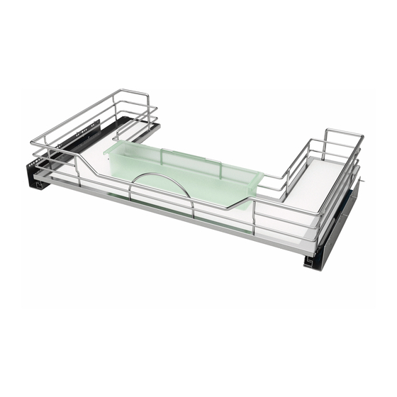
GLIDING DRAWER SYSTEM
TOOLS REQUIRED:
3
mm
Component
Description
No.
No.
A
Basket
B
Slide
A
Logo cap
C
B
No.
ESTIMATED ASSEMBLY TIME:
D
C
5/32x18 Wood Screw
A
D
B
30 MIN
Component
C
Description
No.
D
A
E
B
(5730-450SC-CW-1)
A
Logo cap
C
(5730-450SC-CW-1)
(5730450SC)
A
A
D
5/32x18 Wood Screw
Component
Component
CARE AND MAINTENANCE:
Qty
Description
No.
Qty
Description
No.
Mounting bracket
1
E
Mounting bracket
1
• Clean with a damp cloth and
E
(5730-450SC-CW-1)
Door mounting bracket
1 Set
F
A
Door mounting bracket
1 Set
F
wipe parts dry
2
G
M4x6mm Machine screw
2
G
M4x6mm Machine screw
M4x4.5L Screw (Spare Parts)
16
H
• Lubricate pivot points as
Component
M4x4.5L Screw (Spare Parts)
16
H
needed
Description
Qty
No.
Basket
1
E
Slide
1 Set
F
Logo cap
2
G
16
H
(5786-900SC-CW-1)
A
(5786-900SC-CW-1)
A
(5786900SC)
A
(5786-900SC-CW-1)
A
#2
1 BASKET INCLUDED, 2 UNITS SHOWN
Component
Description
No.
A
Basket
B
Slide
Logo cap
C
D
5/32x18 Wood Screw
A.
Component
Qty
No.
Description
Qty
No.
1
E
(5730-450SC-CW-1)
A
Door mounting bracket
Component
1 Set
F
Basket
1
E
5730
Description
2
G
M4x6mm Machine screw
Slide
1 Set
F
Logo cap
16
M4x4.5L Screw (Spare Parts)
H
2
G
Basket
5/32x18 Wood Screw
16
H
Slide
Logo cap
Qty
No.
5/32(4mm)x18 Pan Head Wood Screw
Basket
1
E
Mounting bracket
Door mounting bracket
Slide
1 Set
F
2
G
M4x6mm Machine screw
M4x4.5L Screw (Spare Parts)
16
H
(5786-900SC-CW-1)
A
Qty
Qty
1 Set
1 Set
5786
1 Set
1 Set
4
4
2
Component
2
B
Description
Qty
Mounting bracket
1 Set
Door mounting bracket
1 Set
M4x6mm Machine screw
4
M4x4.5L Screw (Spare Parts)
2
B.
B.
FOR DOOR MOUNTING ONLY
E
E
INSTALLATION INSTRUCTIONS: GLIDING DRAWER SYSTEM
E
Component
Qty
Description
No.
Mounting bracket
1
E
Door mounting bracket
1 Set
F
2
G
M4x6mm Machine screw
16
H
M4x4.5L Screw (Spare Parts)
Component
No.
Description
Component
Qty
A
Description
Qty
Mounting bracket
1 Set
Mounting bracket
1 Set
Component
1 Set
B
Qty
Door mounting bracket
4
Description
No.
1 Set
M4x6mm Machine screw
2
4
Door mounting bracket
1
F
C
M4x4.5L Screw (Spare Parts)
2
1 Set
G
M4x6mm Machine screw
Component
D
M4x4.5L Screw (Spare Parts)
2
H
Description
Qty
16
I
Small bin
E
Mounting bracket
1 Set
J
Double sided tape
1 Set
1 Set
F
4
2
G
B
H
I
C
J
C
B
B
E
E
I
E
FOR DOOR MOUNTING ONLY
F
F
FOR DOOR MOUNTING ONLY
Qty
1 Set
Parts List
1 Set
C
4
2
B
Description
Component
Description
No.
A
Basket
Shelves
B
Slide
Logo cap
C
C
Slide Set
D
5/32(4mm)x18 Pan Head Wood Screw
Qty
Mounting bracket
E
1 Set
Logo Caps
B
(5730450SC)
4
A
B
4G x 18 mm Pan Head Wood Screws
2
1
Small Bin
2
C
M4 x 4.5 mm Pan Head Screws
FOR DOOR MOUNTING ONLY
Mounting Bracket
B
20180102-1
Door Mounting Bracket
F
E
M4 x 6 mm Machine Screws
D
Double Sided Tape
D
C.
(5786900SC)
D.
A
FOR DOOR MOUNTING ONLY
FOR DOOR MOUNTING ONLY
C
FOR DOOR MOUNTING ONLY
F
F
FOR DOOR MOUNTING ONLY
FOR DOOR MOUNTING ONLY:
H
E
H
H.
G.
F
G
G
F
5786-900-CW-1 (2)
20180102-1
D
Qty
Component
Qty
Description
No.
1
F
Door mounting bracket
1
1 Set
G
M4x6mm Machine screw
M4x4.5L Screw (Spare Parts)
D
2
H
1 Set
16
I
Small bin
C
D
Double sided tape
1 Set
J
2
H
C
16
B
1
D
2
1 Set
20180102-1
1 Set
G
H
H
4
2
H
20180102-1
E.
E
F.
I
H
D
G
G
1/2
F
J
I.
G
H
J.
I-57XX-0118
G
20180102-1
2018
Qty
1 Set
2
4
2
1
2
20180102-1
D
FOR
G
1/2
Advertisement
Table of Contents

Related Manuals for Rev-A-Shelf 5786-900-CW-1


Summary of Contents for Rev-A-Shelf 5786-900-CW-1
- Page 1 GLIDING DRAWER SYSTEM TOOLS REQUIRED: 1 BASKET INCLUDED, 2 UNITS SHOWN 5786-900-CW-1 (2) 20180102-1 Component Component Description Description Mounting bracket Basket 1 Set Parts List Door mounting bracket Slide 1 Set 1 Set Logo cap M4x6mm Machine screw 20180102-1 5/32x18 Wood Screw M4x4.5L Screw (Spare Parts)
- Page 2 FIGURE A CHOOSING THE DESIRED BOTTOM FOR THE UNIT M4 x 4.5mm Screw M4x4.5L Screw Unscrew the M4 x 4.5 mm Pan Head Screws from the bottom of the shelf, choose the desired color by flipping the shelf and reinstall the bottom shelf.
- Page 3 STEP 3 FIGURE D Use the images in Figure D to adjust the slides based on the cabinet thickness of 16 mm, 18 mm, Side Panel or 20 mm. Side Panel 16/18/20 mm 16/18/20 mm 16/18/20 mm 16/18/20 mm 18 mm 20 mm 16 mm 18 mm...
- Page 4 STEP 4. FIGURE F STEP 5 Using measurements from Figure F predrill hole locations, be careful not to drill through door. Attach the door mounting brackets to the cabinet door with (8) 4G x 18 mm Pan Head Screws. The mounting dimensions will vary based on the unit that was purchased.
Need help?
Do you have a question about the 5786-900-CW-1 and is the answer not in the manual?
Questions and answers