Table of Contents
Advertisement
Advertisement
Table of Contents

Subscribe to Our Youtube Channel
Related Manuals for Fancom LM.60i


Summary of Contents for Fancom LM.60i
- Page 1 LM.60i Manual...
- Page 2 Always keep this manual near the motor Note: The original, authoritative version of this manual is the English version produced by Fancom B.V. or any of its subsidiaries, (hereafter collectively referred to as "Fancom"). Subsequent changes to any manual made by any third party have not been reviewed nor authenticated by Fancom.
-
Page 3: Table Of Contents
Addressing ................16 8.1.2. Temperature measurement ............ 16 8.1.3. Independent control ............... 17 8.2. The LM.60i as conventional end station ..........17 8.2.1. Addressing ................17 Built-in emergency battery (optional) ..........18 Adjustment procedure ............... 19 10.1. General ....................19... - Page 4 LM.60i Table of contents 10.2. General information relating to calibration ..........20 10.3. Step 1: Adjusting the limit switches ............22 10.4. Step 2: Adjusting CLOSED position ............. 24 10.5. Step 3: Adjusting OPEN-position ............26 10.6. Step 4: Adjusting PREDEFINED position ..........27 10.7.
-
Page 5: Table Of Contents
LM.60i EC-declaration of compliance EC-declaration of compliance Manufacturer Fancom B.V. Address Industrieterrein 34 City Panningen (the Netherlands) Hereby declares that the: LM.60i Satisfies the conditions set out in: The Low Voltage directive 2006/95/EC According to EN-61010 The Machine directive 2006/42/EC... - Page 6 LM.60i About this manual About this manual This manual has been written for the installer and the user of Fancom actuators and contains information about the installation and working, as well as service to the actuators. For the installer Read this manual carefully and observe all safety instructions before making any installer settings and preparing the actuator for further use.
-
Page 7: Introduction
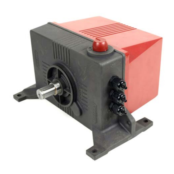
LM.60i 1. Introduction Introduction The Fancom LM.60i is a 24Vac winch motor with built in intelligence. The LM.60i is used in combination with a Fancom control computer to regulate air inlets in the agricultural sector. The LM.60i can be used as a conventional end station, controlled via a 0-10/10-0Volt signal or as an IO-net module in a Fancom IO-Network. -
Page 8: Technical Specifications
LM.60i 2. Technical specs Technical specifications Power supply Mains voltage 24 Vac (± 10%) Emergency voltage 24 Vdc (± 10%) Mains frequency 50/60Hz Max. current used 0.8A Power consumption Battery 2x12Vdc PF input (Power Fail) close contact Control Voltage input (Analogue input) ór... - Page 9 LM.60i 2. Technical specs Accessories (optional) Battery pack (A5160009) 2x12Vdc / 0,8 Ah ∅ 50mm Cable reel (A5450004) ∅ 1 inch Pipe tube connection (A5459011) CE-protection cover (A5459007) Temperature sensor (A5045011) Range –50-+110°C Resolution 0,1°C Manual potentiometer (A5130150) on distance Max.
-
Page 10: Safety Instructions And Warnings
Never touch any rotating parts of the actuator! Check the actuator regularly for correct functioning. Prevent electrostatic discharge (ESD) Fancom cannot be held liable for any damage caused by incorrect mounting and/or non-or partial functioning of the entire installation. If the product in whatever form or version is modified and/or altered, any right to the guarantee and support offered by Fancom will be become null and void. -
Page 11: Mounting And Installation
LM.60i 4. Mounting Mounting and Installation 4.1. Introduction When mounting/installing the module, pay attention to the following points: • Mount the actuator where the weather can have no direct influence; not in direct sunlight, or in places where the temperature can rise to extremes etc. -
Page 12: Mechanical Mounting
LM.60i 4. Mounting 4.2. Mechanical mounting • Used the drilling jig supplied for the correct pattern of holes. • Mount the actuator module solidly on a level surface; preferable with the swivels underneath. If the mounting surface is not level, use the filling plates supplied ( 0.5 resp... -
Page 13: Electrical Connections
Mount all wiring/cables so they cannot be damaged and can easily be replaced in the event of a malfunction. • If metal cable channels are used, Fancom advises earthing the channel at Begin and end of the channel, and as often as possible at other points. -
Page 14: Print Connections
LM.60i 4. Mounting 4.3.2. Print connections Display Operating switch 24 Volt AC Potentiometer (W=Wiper) IO-Net Limit switches Analogue in(0-10V/10-0Vcontrol) Motor or Temp. sensor (IO-net) Connections A+B+C+D are already mounted. A5911664 - GB 100503... -
Page 15: Optional Print Connections
LM.60i 4. Mounting 4.3.3. Optional print connections Batteries (+A1- ; +A2-) Manual Override potentiometer or thermostat (+MAN-) Power Failure (+PF-) 4.3.4. Reversing the rotational direction It may be necessary to reverse the rotational direction of the actuator. To do this exchange the connection wires of •... -
Page 16: Extra Possibilities Lm.60I
24Vac power cannot fail. This UPS has to be provided with powerfail PF- (Normally open) output contact that will short the “PF’-input on the LM.60i, when the regular power fails. The LM.60i will go to the pre-defined position. -
Page 17: Operation
Operation 6.1. Switch The LM.60i has a 5-position switch. The switch is used to choose between automatic (AUT) control or manual, close/open or off (O). Manually operated options work directly on the motor, so do not involve the intelligent module. -
Page 18: Display
The display indicates a possible status of the program (depending on the position of the manual operation on the LM.60i). After the LM.60i has been switched on, 3 characters will be displayed in succession. These characters are the version number of the software (1 character per second). -
Page 19: Alarms
Current limiting activated Note 1: Clear a cancelled alarm by pressing the key in the print. Note 2: A control computer connected to the LM.60i via I/IO-net, can adopt the alarm message, provided this feature is supported. A5911664 - GB 100503... -
Page 20: Control
See appendix 1 for an overview of the addresses 8.1.2. Temperature measurement As IO-network module the LM.60i can measure the temperature itself. This value can be used by the control computer, or to control independently in the case of an emergency. -
Page 21: Independent Control
8.2. The LM.60i as conventional end station 8.2.1. Addressing If the LM.60i is used as a traditional end station it is controlled by a 0-10V or 10-0V voltage signal. In this application temperature measurement is not possible. To enable the analog input to be used for control voltage, the jumpers JP1 must be set to the U position. -
Page 22: Built-In Emergency Battery (Optional)
DIP 7 – Using an internal battery. If the LM.60i is equipped with an internal emergency battery, DIP-7 must be set to OFF to activate the trickle charger. A5911664 - GB 100503... -
Page 23: Adjustment Procedure
- CLOSED-position and the potentiometer that measures the inlet position - OPEN-position - PREDEFINED-position In the event of a power failure the LM.60i controls to a pre- defined position The motor can be sent to the required position using the 5-position manual operation switch. -
Page 24: General Information Relating To Calibration
LM.60i 10. Adjustment 10.2. General information relating to calibration Press the button on the print to start the adjustment procedure. After 2 seconds a counter on the display will start to count from “0”. Release the button as soon as the required option appears on the display: •... - Page 25 LM.60i 10. Adjustment Attention! Ensure the steel cable is wound at least once around the drum when the air inlet is fully open. The minimum length of stroke from Open to Closed must be a minimum of 0.8 revolutions (12.5 cm).
-
Page 26: Step 1: Adjusting The Limit Switches
10.3. Step 1: Adjusting the limit switches Careful! Check that the electrical connections are correct before starting to adjust the limit switches. Open the LM.60i housing. Ensure the cam discs (1 and 4) are loose on the shaft, so the discs can be twisted. - Page 27 LM.60i 10. Adjustment Fig. 2: Limit switches Cam disc closed position Screw to fix cam disc closed position Worm wheel for fine tuning closed position Cam disc open position Screw to fix cam disc open position Worm wheel for fine tuning open position...
-
Page 28: Step 2: Adjusting Closed Position
LM.60i 10. Adjustment 10.4. Step 2: Adjusting CLOSED position Set the manual operation switch to position (). Allow the air inlet to close fully. With 0-10V or 10-0 V control, ensure that the analog output of the connected outputs is 1%. - Page 29 LM.60i 10. Adjustment Display Status/action Signal too high, turn potentiometer further to the left Signal too low, turn potentiometer further to the right. Signal OK, proceed with the next step. A5911664 - GB 100503...
-
Page 30: Step 3: Adjusting Open-Position
LM.60i 10. Adjustment 10.5. Step 3: Adjusting OPEN-position Set the manual operation switch to position () and allow the inlet to open to the required position. With 0-10V or 10-0 V control, ensure that the analog output of the connected control computer outputs 99%. -
Page 31: Step 4: Adjusting Predefined Position
LM.60i 10. Adjustment 10.6. Step 4: Adjusting PREDEFINED position Use the manual operation switch to set the air inlet in the position it must assume in the event of a power failure. Press the button until “3” appears on the display. -
Page 32: Appendix 1: Table Of I/O Addresses
LM.60i Appendix 1 Appendix 1: Table of I/O addresses I/O-Address Restart the module after changing a network address. A5911664 - GB 100503... -
Page 33: Appendix 2: Connecting The Io Network
The order of network modules is not important. Wiring of I/O-network: Fancom Greenlink cable (A1732005) UTP 1x2x0.8 mm (unshielded twisted pair) Max. length of I/O-network 900m Connect Fancom equipment according to the prevailing standards of the local electricity company. A5911664 - GB 100503... -
Page 34: Appendix 3: Mountings
LM.60i Appendix 3 Appendix 3: Mountings A5911664 - GB 100503... - Page 35 LM.60i Appendix 3 Mounting cable reel A5911664 - GB 100503...
- Page 36 LM.60i Appendix 3 2 Mounting steel wire Feed the cable through the opening Place the retainer clamp at the end of the steel cable VERY IMPORTANT: Wind at least 1 stroke before loading the cable. A5911664 - GB 100503...
- Page 37 LM.60i Appendix 3 3 Mounting CE-protection cover on cable reel A5911664 - GB 100503...
- Page 38 LM.60i Appendix 3 4 Mounting pipe/chain coupling (1”) A5911664 - GB 100503...
-
Page 39: Appendix 4: Wiring Diagram
LM.60i Appendix 4 Appendix 4: Wiring diagram Manual Manual switch Switch I/O-net I/O-net Terminal resistor Terminal resistor 1 2 3 4 5 6 Temp. Temp Accu 1 (Option) Accu 2 Open M1 M2 Close (Option) 24 Vac 24 Vac Power supply Power`supply 2x0.8 mm...
Need help?
Do you have a question about the LM.60i and is the answer not in the manual?
Questions and answers