Table of Contents
Advertisement
Quick Links
Advertisement
Table of Contents

Subscribe to Our Youtube Channel
Related Manuals for Fancom Aura 14


Summary of Contents for Fancom Aura 14
- Page 2 N.B.: The original, authentic version of this manual is the English version produced by Fancom B.V. or one of its daughter companies (referred to further as Fancom). Any modifications introduced to this manual by third parties have neither been checked nor approved by Fancom. Modifications are taken by Fancom to include translations into languages other than English and the insertion and/or deletion of text and/or illustrations to/from the original contents.
- Page 3 Installing the Aura 14 ..........................15 Determine location ........................15 Mount the Aura 14 ........................15 Connect the Aura 14 ........................16 Connect the Aura 14 to FNet ......................17 Installer settings ............................18 Overview............................18 CFG .............................. 20 SYS .............................. 21 INS ...............................
- Page 4 Always keep the manual close to the control computer. Climate manual This manual supplies information about the basic climate principles (the manual is available on the Fancom extranet and it can be ordered separately). The following symbols are used in this manual: Tips and suggestions.
- Page 5 The guarantee does not apply if this product is installed in any other way than is indicated by Fancom and if the product's motor has been opened and changes have been made to the product.
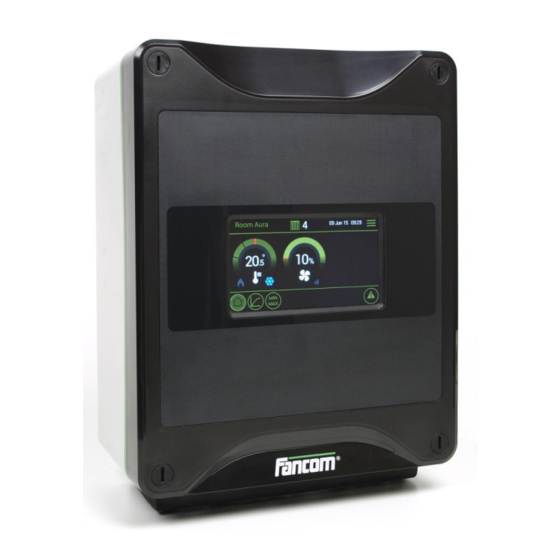
- Page 6 Aura 14 Aura 14 The Aura 14 controller is used for climate control in the agricultural sector. It regulates ventilation and heating for one section. The Aura 14 can be used with various ventilation systems: ProFlow NatuFlow ...
- Page 7 Aura 14 Using the Aura 14 This chapter describes the main parts and the operation of the Aura 14. The Aura 14 can be operated on the touch screen. Touch screen The Aura 14 screens are divided in three sections: Title bar: Displays the name of the selected screen (e.g.
- Page 8 Aura 14 User settings With daily management you can set the temperature and ventilation settings manually. If a curve is used, the daily management overwrites the settings temporary. The left dial displays the actual temperature. The right dial displays the actual ventilation. In both dials the actual control value is displayed as a red marker.
- Page 9 Aura 14 User settings The heating control ensures it does not become too cold in the section. If the temperature drops below the set value, the computer will make a correction. Dial 1 Setting the setpoint heating. Setting the minimum ventilation temperature.
- Page 10 Aura 14 User settings Dial 2 Readout of the control value (left) and a readout of the actual ventilation. Readout of the actual position of the vortex damper. Readout of the actual position of the air inlet.
- Page 11 The day number is a counter increased by the controller each day at midnight by one up to a maximum of 999. If the day number is 0 it will not change. The Aura 14 then controls without the curve, even if the bending points have been set.
- Page 12 Aura 14 User settings Readout of the highest, actual and lowest measured temperatures of the section. Followed by the time of measurement. Readout of the highest, actual and lowest measured temperatures of the extra temperature sensor. Followed by the time of measurement.
- Page 13 Aura 14 Alarm Request the alarm overview using the alarm button There are two buttons: Alarm overview to readout the status. Alarm settings to change the alarm settings. Types of alarm There are two types of alarm: LOUD: A loud alarm means a report is shown on the screen and a siren is sounded (if connected). Take action immediately.
- Page 14 Aura 14 Alarm Message Readout of the alarms (see table below). Temperature alarms Alarm Action Min.room temp. (abs) Minimum alarm Max.room temp. (abs) Check wiring and sensors. Min.room temp. (dif) Check if the heater works properly (if available).
- Page 15 The alarm message states that the alarm has been disabled and is active again. The message will be cleared from the alarm overview. Fancom advises testing the alarm weekly for correct functioning. During the test the control computer will give a loud alarm.
- Page 16 Aura 14 Alarm Abs. Maximum alarm If the house temperature is higher than the set Abs. maximum alarm, the control computer will give a maximum temperature alarm. Max. difference alarm The control computer gives a maximum temperature difference alarm if the house...
- Page 17 Aura 14 Alarm Calc. start temp. ventilation: 20ºC Calculated bandwith: 4ºC Ventilation is maximum at: 24ºC Setpoint therm. ctrl: 24ºC Outside temperature: 25ºC Max. difference alarm: 3ºC Max. difference alarm: 3ºC Calculated alarm limit: 27ºC Calc. alarm limit: 27ºC Absolute maximum alarm: 26ºC...
- Page 18 Never mount the Aura 14 in a humid and/or dusty room and certainly not in the room where the animals are present. Mount the Aura 14 at such a height that you can control the Aura 14 easily (eye level) and square on a solid backing. The swivels should be positioned at the bottom.
- Page 19 Check that the mains voltage and frequency, for which this computer is suitable, correspond to the mains voltage and frequency on site. Be sure that the Aura 14 is properly grounded. When using metal cable trays, grounding at one point of the tray is recommended.
- Page 20 Control computers 2 and 3 are looped. These looped control computers do not require a terminal resistor. The Fancom Greenlink cable (UTP 1x2x0.8mm, unshielded twisted pair) used to wire the FNET and I/O net. Maximum cable length = 1200 meters.
- Page 21 Aura 14 Installer settings The paragraph below shows the settings of the most used applications in the Aura 14. Make the settings in the installation menu. Menu Description Example Configuration settings Aura system settings System settings System settings application (how to use the control computer).
- Page 22 Ventilation DSR Type Energy-saving Mechanical If the Aura 14 is used in a central air exhaust system, Analog output 1 is used for the Fancom ATM-unit. If a Fancom ATM-unit is used, make the following settings: Analog output 1...
- Page 23 (like all the other connected computers). To avoid peak load on the net by several computers activating simultaneously, Fancom advises always entering a computer number. Temperature unit Setting of the unit of temperature (Celsius / Fahrenheit).
- Page 24 Aura 14 Installer settings Language Setting of the software language. Net frequency Readout of the net frequency (50Hz of 60Hz). After changing the net frequency, switch the computer off and on again. Communication Setting of the communication level master or slave (Master/Slave). The master is the computer responsible for communication.
- Page 25 Aura 14 Installer settings Alarm thermal control Setting of the sensor thermal control alarm: No alarm With outside temp: the controller calculates the maximum difference alarm, taking a high outside temperature into account. Without outside temp: the controller calculates the maximum difference alarm, not taking a high outside temperature into account.
- Page 26 Pre-control 1 Pre-control 2 Pre-control 1 & 2 An Aura 14 cannot control a boiler, but transmits the heat demand via Fnet communication to a controller that can. With types Pre-control Pre-control Pre-control 1 & 2 the Aura 14 determines the heat demand as the difference between the measured temperature and the control value.
- Page 27 None: No influence on central air control. inlet: The Aura 14 transmits the control value of the total ventilation to the controller responsible for controlling central ventilation based on the average (calculated) ventilation of all assigned sections. This control is particularly suitable for a central air inlet.
- Page 28 Calibration value 1% / If triac control is used for ventilation control, set the triac control range here. Fancom 99% ventilation advises always carrying out 1% and 99% calibration, in connection with control without DSR feedback or an automatic switch from control with DSR feedback to control without DSR feedback (if DSR feedback fails).
- Page 29 Ventilation DSR 0-10V ITM endstation 10-0V If the Aura 14 controls the Fancom ProFlow system, assign Vortex Pro/Natu 10-0V and set Type triac to Ventilation. Analog output 1 Setting of the correction factor. If there is a difference between the measured and the...
- Page 30 Aura 14 Installer settings Analog output 1 Setting of the minimum position (by using heating or thermal) or correction buffer (by Correction buffer / using other control types). Minimum pos. Correction buffer: Each control time the computer registers the difference between the measured and control value and adds this to any previous differences.
- Page 31 Aura 14 Installer settings Analog output 3 Setting if analog output 3 is used: Type None Air inlet combi 10-0V Air inlet combi 0-10V Heating 0-10V Heating 10-0V Thermal control 0-10V Thermal control 10-0V ...
- Page 32 Aura 14 Installer settings DSR alarm Setting how the alarm should be given with a DSR feedback alarm: Loud alarm: report + alarm relay Silent alarm: report only alarm: no alarm Use options Combi position thru Combi air inlet to set the combi-table.
- Page 33 Aura 14 Installer settings Combi relay Setting of the relay to be switched, when the position set at is Active. The left field indicates if relay 1 must switch on/off; the right field indicates this for relay 4. Relay to be switched...
- Page 34 Aura 14 Installer settings Assignment Rel 1-4 Setting of the relay functions: Nbr. Relay 1 Relay 2 Relay 3 Relay 4 Combi Combi Combi Combi Combi Combi Combi Heating (on/off) Combi Combi Combi Thermal (on/off) Combi Combi Thermal (on/off) Heating (on/off)
- Page 35 Aura 14 Installer settings Type Setting which ventilation concept is used for control: Energy-saving Natural: ProFlow/NatuFlow ventilation system with possibility to switch to natural ventilation. Energy-saving Mechanical: ProFlow/NatuFlow ventilation system without possibility to switch to natural ventilation.
- Page 36 Aura 14 Appendix: System connection settings Concept Vent. Air inlet Vortex Heating Therm. contr. Infl. Decrease Infl. damper outside time centr. temp. outside vent. temp. infl. 0 Standard Triac 10-0V 10-0V On/Off (relay 4) On/Off (relay 3 without DSR (analog 1)
- Page 37 Aura 14 Appendix: Connection diagram Aura 14...
- Page 38 Aura 14 Appendix: Connection diagram Aura 14...
- Page 39 Aura 14 Appendix: Connection diagram Aura 14...
- Page 40 Aura 14 Appendix: Connection diagram for alarm...
- Page 41 Weight (unpacked) 2.4kg Ambient climate Operating temperature range 0°C to +40°C Storage temperature range -10°C to +50°C Relative humidity <95%, uncondensed Communication Fancom FNet for inter-communication of computers and PC connection PC*. * See connection diagram for connections and wiring.
- Page 42 Aura 14 Technical specifications Aura board Touch screen Powerboard FCA Trix board T-5 Powerboard FCA...
- Page 43 Aura 14 Technical specifications IO Net - IO Net + Fnet 1- Fnet 1+ Fnet 2- Fnet 2+ SD Card...
- Page 44 Aura 14 Appendix: EG-declaration of compliance Manufacturer Fancom B.V. Address: Industrieterrein 34 Place: Panningen (the Netherlands) Hereby declares that: Aura 14 Satisfies the conditions of: The Low Voltage Directive 2014/35/EU according to EN-61010 the EMC Guideline, directive 2014/30/EU Emission and immunity according to NEN-EN-IEC 61326...
Need help?
Do you have a question about the Aura 14 and is the answer not in the manual?
Questions and answers