
Related Manuals for Moxa Technologies ioLogik 4000 Series


Summary of Contents for Moxa Technologies ioLogik 4000 Series
- Page 1 4000 Series User’s Manual Edition 4.1, September 2016 www.moxa.com/product © 2016 Moxa Inc. All rights reserved.
-
Page 2: Copyright Notice
4000 Series User’s Manual The software described in this manual is furnished under a license agreement and may be used only in accordance with the terms of that agreement. Copyright Notice © 2016 Moxa Inc. All rights reserved. Trademarks The MOXA logo is a registered trademark of Moxa Inc. -
Page 3: Table Of Contents
Table of Contents Overview ............................1-1 ioLogik 4000 System Overview ......................1-2 Package List ............................1-2 Product Features ..........................1-2 Product Specifications ......................... 1-3 Hardware Installation ........................2-1 System Architecture ..........................2-2 Connecting the Network Adapter to I/O Modules ..................2-3 Appearance .......................... - Page 4 RTD ............................4-7 Thermocouple ..........................4-8 MXIO DLL Library ..........................5-1 Overview ............................5-2 MXIO Function Groups ......................... 5-2 Pinouts and Cable Wiring ........................A-1 Port Pinout Diagrams .......................... A-2 Ethernet Port Pinouts ........................A-2 Serial Port Pinouts ........................A-2 Ethernet Cable Wiring Diagrams ......................
-
Page 5: Overview
Overview The ioLogik 4000 is a stand-alone Active Ethernet I/O server that can connect sensors and on/off switches for automation applications over Ethernet and IP-based networks. The following topics are covered in this chapter: ioLogik 4000 System Overview Package List ... -
Page 6: Iologik 4000 System Overview
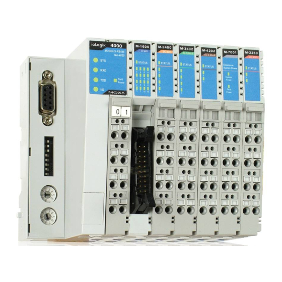
ioLogik 4000 Overview ioLogik 4000 System Overview ioLogik 4000 is a Network I/O Server that can connect sensors and on/off devices in any combination and can transfer the captured data or device status to a host computer via an Ethernet or RS-485/232 network. ioLogik 4000 consists of two main parts. -
Page 7: Product Specifications
ioLogik 4000 Overview Product Specifications ioLogik 4000’s detailed specifications are available in the software’s product specification help files. Refer to the help file for more information. Models supported by this manual are: Model Name Network Adapter NA-4010 Ethernet Network Adapter Modbus/TCP NA-4020 RS-485 Network Adapter Modbus/RTU NA-4021... -
Page 8: Hardware Installation
Hardware Installation This chapter includes information about installing ioLogik 4000 I/O Server, including the Ethernet Network Adapter and RS-485, RS-232 Network Adapters. The following topics are covered: The following topics are covered in this chapter: System Architecture Connecting the Network Adapter to I/O Modules ... -
Page 9: System Architecture
ioLogik 4000 Hardware Installation System Architecture The ioLogik 4000 Slice-type I/O Server consists of a Network Adapter that supports Ethernet, RS-485 or RS-232, and up to 32 I/O modules. ioLogik 4000’s Network Adapter is the brains of the system. Its responsibility is to collect information from each I/O module, and decide the parameters for the I/O module’s operation. -
Page 10: Connecting The Network Adapter To I/O Modules
ioLogik 4000 Hardware Installation Connecting the Network Adapter to I/O Modules This section describes how to install ioLogik 4000 I/O modules with the Network Adapter. Appearance... -
Page 11: Installing I/O Modules On A Din-Rail
ioLogik 4000 Hardware Installation Installing I/O Modules on a DIN-Rail Step 1: Align the I/O module and Network Adapter side by side, making sure the upper and lower rails are hooked. Step 2: Push the I/O module along the inner rail until it touches the DIN-Rail, and then push hard to clip it onto the DIN-Rail. -
Page 12: Removing I/O Modules From A Din-Rail
ioLogik 4000 Hardware Installation Removing I/O Modules from a DIN-Rail Step 1: Use your finger or a screw driver to push down the tab located on the lower part of the module. Step 2: Pull out the I/O module. -
Page 13: Installing An Rtb (Removable Terminal Block)
ioLogik 4000 Hardware Installation Installing an RTB (Removable Terminal Block) Removing the RTB from the I/O module Pull hard to remove the plastic belt from the RTB. Installing the RTB on the I/O module Align the lower part of the terminal block with the I/O module, and then push the RTB so that it fits into the I/O module. -
Page 14: Connecting To The Network
ioLogik 4000 Hardware Installation Connecting to the Network NA-4010 Ethernet Network Adapter NA-4010 Ethernet Network Adapter supports standard 10/100 Mbps Ethernet. For first time users, we recommend that you link from your host computer to NA-4010 over a local Ethernet network to take care of IP and system configuration. -
Page 15: Na-4020 Rs-485 Network Adapter
ioLogik 4000 Hardware Installation NA-4020 RS-485 Network Adapter For first time installation, we recommend that you connect the NA-4020 RS-485 Network Adapter to a host computer running the ioAdmin utility to take care of configuration. Once the I/O system is configured, you can move the entire system to the field. -
Page 16: Led Indicators
ioLogik 4000 Hardware Installation LED Indicators This section describes the LED indicators on the ioLogik 4000 system. LED Indicators for Network Adapters The NA-4010 Ethernet Network Adapter has 5 LED indicators, as described in the following table. LED Name LED Color LED Function No power. -
Page 17: Led Indicators For I/O Modules
ioLogik 4000 Hardware Installation The NA-4020/21 RS-485, RS-232 Network Adapter has 5 LED indicators, as described in the following table. LED Name LED Color LED Function No power. Green Steady On: Operating condition normal. Red/Green Toggling: Modbus error (e.g., watch dog timer error) Steady On: EEPROM checksum error. -
Page 18: When To Use The Power Expansion Module
When to Use the Field Power Distributor Most of the field power DIO/AIO modules for the ioLogik 4000 series are 24 VDC. If you need to connect 48 VDC or 110 VAC, 230 VAC digital input or output modules, you must use the Field Power Distributor to isolate different field powers within a single ioLogik 4000 system. -
Page 19: When To Use The Potential Distributor
ioLogik 4000 Hardware Installation When to Use the Potential Distributor Three types of Potential Distributor module provide extra wiring points, such as shielding ground, field power 0V, and field power 24V. For example, the 8-channel digital input (sink type) module itself does not have a 24V wiring point. You may add a 24V Potential Distributor for easy wiring. -
Page 20: Getting Started
Getting Started This chapter introduces the method you should follow when configuring the ioLogik 4000 Ethernet I/O system and ioLogik 4000 RS-485/232 I/O system. The following topics are covered in this chapter: Installing ioAdmin Utility Configuring the NA-4010 Ethernet I/O System ... -
Page 21: Installing Ioadmin Utility
ioLogik 4000 Getting Started Installing ioAdmin Utility ioAdmin can be downloaded from Moxa’s website. 1. Installing ioAdmin from website: a. First click on the following link to access the website’s search utility: http://www.moxa.com/support/search.aspx?type=soft b. When the web page opens, enter the model name of your product in the search box. c. - Page 22 ioLogik 4000 Getting Started 5. To set a new IP address for an Ethernet I/O server, run ioAdmin, and then click on Reset NA 4010 Network Adapter IP. Enter the MAC Address of the NA-4010, and the new IP address. To complete the configuration, click on Reset.
-
Page 23: Linking The Ethernet I/O System To Ioadmin
ioLogik 4000 Getting Started 7. Note that this approach only applies when the host computer and the Ethernet Network Adapter are on the same subnet. For first time users, the default IP is 192.168.127.254. Linking the Ethernet I/O System to ioAdmin Before using ioAdmin to link to the Ethernet I/O system, make sure the Ethernet connection for both the I/O server and host computer are working normally. - Page 24 ioLogik 4000 Getting Started Select Ethernet adapter, and then click on Start Search. ioAdmin will start searching for installed NA-4010’s on the network. The Auto Search function can only find Ethernet I/O Servers that are on the same subnet. To connect to Ethernet I/O Servers outside the subnet, you will need to add the Ethernet I/O server manually.
-
Page 25: Password Protection
ioLogik 4000 Getting Started After using auto search, or keying in the ioAdmin IP address manually, the Ethernet I/O servers that were located will appear as follows. The left frame of ioAdmin shows the I/O Servers connected to the network that were located by the search process. -
Page 26: Reset To Default
ioLogik 4000 Getting Started Reset to Default The Network Adapter settings, including IP address, netmask, gateway, watchdog timer, I/O module safety status, and temperature sensor parameters are stored in the network adapter. Right click on the target I/O server, and then click on Reset to Default to proceed. You may need to wait 10 seconds or longer. -
Page 27: Network
ioLogik 4000 Getting Started Note that this function requires disconnected from the ioLogik to activate. Network Click on the Network Adapter’s Network tab to change the IP Address, Network Mask, Gateway, and MAC address. There are two options for IP configuration: Bootp and ARP. We strongly recommend that you leave ARP ON to reserve the opportunity to modify the IP address when necessary. -
Page 28: Tcp Socket Timeout Interval
ioLogik 4000 Getting Started TCP Socket Timeout Interval The Socket timeout interval in the System menu is used to configure the timeout for each Modbus/TCP query from the host computer to the Ethernet Network Adapter. The unit is seconds. Watchdog Timer The Watchdog timer function is used to monitor the Modbus/TCP connection between the Ethernet Network Adapter and the host computer. -
Page 29: Firmware Upgrade
ioLogik 4000 Getting Started Firmware Upgrade NA-4010’s firmware can be updated via Ethernet. To upgrade the firmware, click on “Firmware Upgrade” tab. Click on the file icon and select the firmware. Press Upgrade when you’re ready. During the firmware upgrade, DO NOT turn the ioLogik 4000’s power off. -
Page 30: Checking Na-4010'S Ethernet I/O Status Via Web Browser
ioLogik 4000 Getting Started Checking NA-4010’s Ethernet I/O Status via Web Browser Entering the Web Console The main configuration interface for ioLogik 4000 relies on ioAdmin utility. However, for NA-4010 Ethernet Network Adapter’s web console, information for basic system status is available. Enter the IP address of the Ethernet I/O server in Internet Explorer. -
Page 31: Configuring Na-4020/4021'S Rs-485/Rs-232 I/O System
ioLogik 4000 Getting Started Click on the slot number to see the status of each module. The following example is for the thermocouple module. Configuring NA-4020/4021’s RS-485/RS-232 I/O System Setting Communication Parameters For first time users, link NA-4021’s RS-232 Network Adapter to the host computer. Make sure the computer is equipped with an RS-232 communication port. - Page 32 ioLogik 4000 Getting Started There is a DIP switch on NA-4020/4021’s front panel that allows you to configure the parameters manually. DIP Switch Con figuration Table Configuration Settings Baud Rate 1200 bps 2400 bps 4800 bps 9600 bps 19200 bps 38400 bps 57600 bps 115200 bps...
-
Page 33: Linking The Rs-485/232 I/O Server To Ioadmin
ioLogik 4000 Getting Started The next step is to configure the Unit ID for the I/O Server. In a Modbus/RTU/ASCII serial network, each node must have a unit ID that ranges from 01 to 99. Use a screw driver to rotate the switch and set the Unit ID. The upper switch represents the high digit, whereas the lower switch represents the low digit. - Page 34 ioLogik 4000 Getting Started Click Port Settings to configure the COM port and baud rate, data bit stop bit, and parity for further communication. Click Start Search to search for connected RS-485 or R-232 I/O Servers. To add RS-485/232 I/O Servers to the ioAdmin manually, click the right mouse button, and then click on ioLogik in the left ioAdmin frame.
- Page 35 ioLogik 4000 Getting Started Once the RS-485/232 I/O Server is connected with ioAdmin, the following screen will appear. 3-16...
-
Page 36: Password Protection
ioLogik 4000 Getting Started The left frame of ioAdmin shows all I/O Servers found on the network. The upper right frame indicates the combination of all I/O modules by slot number. The lower right frame lists detailed information for installed I/O modules. -
Page 37: Restarting The System
ioLogik 4000 Getting Started Restarting the System In general, your don’t need to restart the I/O server when changing I/O module configurations. However, when the I/O Server indicates an I/O error, you may use this function to restart the I/O Server system remotely. Right click on the target I/O server and then click on Restart System to proceed. -
Page 38: Modbus Address Mapping
ioLogik 4000 Getting Started Modbus Address Mapping Finding a Modbus Address for I/O Channels The Modbus Address for each I/O channel is arranged dynamically by the Network Adapter according to the slot sequence and the type of I/O module. Changing Ethernet Network Adapter to RS-485 or RS-232 Network Adapters will not change the Modbus address mapping. -
Page 39: Configuring I/O Modules
Configuring I/O Modules In this chapter, we describe the common features related to using ioAdmin to configure I/O modules. The following topics are covered in this chapter: Overview On-Line Wiring Guide Digital Input Module Digital Output Module ... -
Page 40: Overview
ioLogik 4000 Configuring I/O Modules Overview This Chapter describes common features of ioAdmin for configuring I/O modules. On-Line Wiring Guide ioAdmin has a graphical interface that features the “What You See Is What You Install” philosophy. ioLogik 4000 is easy-to-use, and ioAdmin comes with an on-line I/O wiring guide that makes your job easier than ever. Use the mouse to move the cursor over any of the I/O modules and then click on the right mouse button to display a “Wiring Guide”. -
Page 41: Digital Input Module
ioLogik 4000 Configuring I/O Modules Digital Input Module ioAdmin can monitor the status of each digital input channel. We use M-1800 to illustrate. To check the DI channel status, click on the I/O module in main page to show the I/O status on the “I/O Status” tab. To check the Modbus Address, click on the “Modbus Address”... -
Page 42: Digital Output Module
ioLogik 4000 Configuring I/O Modules Digital Output Module ioAdmin can monitor the status of each digital output channel. We use M-2404 to illustrate. To check the DI channel status, click on the I/O module in the main page. You’ll see the I/O status on the “I/O Status” tab. To check the Modbus Address, click on the “Modbus Address”... -
Page 43: Analog Input Module
ioLogik 4000 Configuring I/O Modules You can test to make sure the digital output channel works over the network. Click on the”Test” tab in the “Config” page. Press the switch, and then press “Test.” At this point, you can change the status of the digital output point. -
Page 44: Analog Output Module
ioLogik 4000 Configuring I/O Modules Analog Output Module This section describes how to configure an analog output module. We’ll use M-4211 to illustrate. To check the status of an analog output channel, click on the I/O module in the main page. You’ll see the I/O status on the “I/O Status”... -
Page 45: Temperature Sensing Modules
ioLogik 4000 Configuring I/O Modules You may test if the analog output channel really works over the network. Click on the “Test” tab on the “Config” page. Scroll the output level, and then press “Test.” At this point, you can change the level of the analog output point. -
Page 46: Thermocouple
ioLogik 4000 Configuring I/O Modules The RTD module supports different kinds of temperature sensor. To configure the sensor type, click on config. On this page, you may set up the sensor types and temperature unit. Note that the configuration applies to all channels in the same module. - Page 47 ioLogik 4000 Configuring I/O Modules The thermocouple module supports different kinds of temperature sensor. To configure the sensor type, click on config. On this page, you may set up the sensor types and the temperature unit. Note that the configuration applies to all channels in the same module.
-
Page 48: Mxio Dll Library
MXIO DLL Library The following topics are covered in this chapter: Overview MXIO Function Groups... -
Page 49: Overview
ioLogik 4000 MXIO DLL Library Overview What is MXIO DLL Library? MXIO DLL Library is a Windows library especially designed for programmers who are not familiar with Modbus protocol, but who need to create applications to get real world temperature, data, and on/off control signals. MXIO DLL supports Visual Basic, Visual C++, and Borland C++ Builder. -
Page 50: Pinouts And Cable Wiring
Pinouts and Cable Wiring The following topics are covered in this appendix: Port Pinout Diagrams Ethernet Port Pinouts Serial Port Pinouts Ethernet Cable Wiring Diagrams... -
Page 51: Port Pinout Diagrams
ioLogik 4000 Pinouts and Cable Wiring Port Pinout Diagrams Ethernet Port Pinouts Signal Serial Port Pinouts NA-4020 RS-485 Network Adapter Pin Assignment. NA-4021 RS-232 Network Adapter Pin Assignment... -
Page 52: Ethernet Cable Wiring Diagrams
ioLogik 4000 Pinouts and Cable Wiring Ethernet Cable Wiring Diagrams...
Need help?
Do you have a question about the ioLogik 4000 Series and is the answer not in the manual?
Questions and answers