Rigol DS6000 Series Service Manual
Hide thumbs
Also See for DS6000 Series:
- User manual (298 pages) ,
- Quick manual (41 pages) ,
- Application note (12 pages)

Related Manuals for Rigol DS6000 Series


Summary of Contents for Rigol DS6000 Series
- Page 1 RIGOL Service Guide DS6000 Series Digital Oscilloscope Feb. 2014 RIGOL Technologies, Inc.
-
Page 3: Guaranty And Declaration
Notices RIGOL products are protected by patent law in and outside of P.R.C. RIGOL reserves the right to modify or change parts of or all the specifications and pricing policies at company’s sole decision. Information in this publication replaces all previously corresponding material. -
Page 4: Safety Requirement
Do Not Operate With Suspected Failures. If you suspect damage occurs to the instrument, have it inspected by qualified service personnel before further operations. Any maintenance, adjustment or replacement especially to circuits or accessories must be performed by RIGOL authorized personnel. DS6000 Service Guide... - Page 5 The battery must not be exposed to high temperature or in contact with fire. Keep it out of the reach of children. Improper change of battery (note: lithium battery) may cause explosion. Use RIGOL specified battery only. Handling Safety Please handle with care during transportation to avoid damages to buttons, knob interfaces and other parts on the panels.
-
Page 6: Safety Terms And Symbols
RIGOL Safety Terms and Symbols Terms in this Manual. These terms may appear in this manual: WARNING Warning statements indicate the conditions or practices that could result in injury or loss of life. CAUTION Caution statements indicate the conditions or practices that could result in damage to this product or other property. -
Page 7: Ds6000 Series Overview
RIGOL DS6000 Series Overview Being a multifunctional and high performance digital oscilloscope, DS6000 delivers a perfect combination of easy-to-use and various function features as well as outstanding specifications to help users to fulfill their tasks more quickly. Main features: 1 GHz or 600 MHz bandwidth. -
Page 8: Table Of Contents
Guaranty and Declaration ................I Safety Requirement ..................II General Safety Summary ................II Safety Terms and Symbols ................. IV DS6000 Series Overview ................V Chapter 1 Disassemble and Assemble ............ 1-1 Disassemble and Assemble Notices ............1-1 Outside View Drawing of the Instrument ............ 1-2 Disassemble the Rear Cover .............. -
Page 9: Chapter 1 Disassemble And Assemble
RIGOL Chapter 1 Disassemble and Assemble Chapter 1 Disassemble and Assemble Disassemble and Assemble Notices Notices: Do not disassemble the instrument unless for working requirement. Only authorized personnel can disassemble the instrument. Cut off the power supply before disassembling the instrument. -
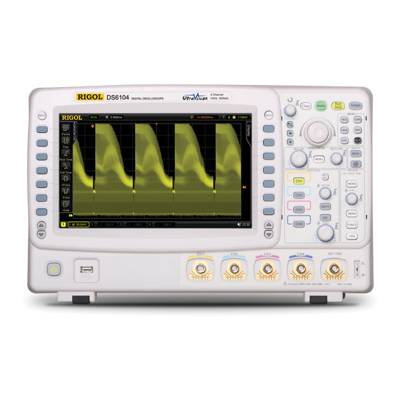
Page 10: Outside View Drawing Of The Instrument
RIGOL Chapter 1 Disassemble and Assemble Outside View Drawing of the Instrument The figure below is the outside view drawing of DS6000 (four-channel). You need to get a basic understanding of the main parts of the instrument before disassembling and assembling the instrument. When disassembling or assembling the instrument, take care not to scratch the surfaces of the parts. -
Page 11: Disassemble The Rear Cover
RIGOL Chapter 1 Disassemble and Assemble Disassemble the Rear Cover ① ① Rear Cover ② Figure 1-2 Disassemble the Rear Cover Part Explanations: ① 2 (M3*8 pan head torx bi-metal flat spring machine) screws at the handle groove. ② 2 (M3*10 countersunk head torx machine) screws at the bottom of the cover. -
Page 12: Disassemble The Rear Metal Cover
RIGOL Chapter 1 Disassemble and Assemble Disassemble the Rear Metal Cover ① ① ① ① ① ① Rear Metal Cover ① Figure 1-3 Disassemble the Rear Metal Cover Part Exaplanation: ① 17 (M3*6 countersunk head torx machine) screws fixing the front metal panel and rear metal cover. -
Page 13: Disassemble The Fan&Power Socket
RIGOL Chapter 1 Disassemble and Assemble Disassemble the Fan&Power Socket ② ② ② ② ② ② Power Socket ① ① ② ② Figure 1-4 Disassemble the Fan and Power Socket Part Explanations: ① 2 (M3*10 countersunk head torx machine) screws fixing the power socket. -
Page 14: Disassemble The Power Supply&Interface Board
RIGOL Chapter 1 Disassemble and Assemble Disassemble the Power Supply&Interface Board Power Suuply ① ① ① ② ① ② ② Interface Board Figure 1-5 Disassemble the Power Supply and Interface Board Part Explanations: ① 4 (M3*10 pan head torx bi-metal flat spring machine) screws fixing the power supply. - Page 15 RIGOL Chapter 1 Disassemble and Assemble Figure 1-6 Positions of the Power Supply and Battery Interfaces Pay attention to the positions of the power supply and battery interfaces when assembling the power supply. Wrong connection might result in main board damage.
-
Page 16: Disassemble The Front Panel
RIGOL Chapter 1 Disassemble and Assemble Disassemble the Front Panel ② ② ② ② ① Knobs ② ② ② Figure 1-7 Disassemble the Front Panel Part Explanations: ① 7 knobs. ② 7 (M3*10 pan head torx machine) screws fixing the front panel. - Page 17 RIGOL Chapter 1 Disassemble and Assemble a) When removing the knobs, you are recommended to prize out the knobs using tools similar to the lever. Besides, it is recommended to place a soft washer at each force-bearing point to avoid damaging the button film and knobs.
-
Page 18: Disassemble The Lcd&Patch Board
RIGOL Chapter 1 Disassemble and Assemble Disassemble the LCD&Patch Board Patch Board ① ① ① ② ① ① ① Figure 1-8 Disassemble the LCD and Patch Board Part Explanations: ① 6 (M3*8 pan head torx bi-metal flat spring machine) screws fixing the LCD. - Page 19 RIGOL Chapter 1 Disassemble and Assemble Figure 1-9 Direction of the Patch Board Pay attention to the direction of the patch board when installing the patch board. DS6000 Service Guide 1-11...
-
Page 20: Disassemble The Buttons
RIGOL Chapter 1 Disassemble and Assemble Disassemble the Buttons ① ① ① ① ① ① ① Figure 1-10 Dsiassemble the Buttons Part Explanation: ① 4 screws fixing the left keyboard, 5 (M3*6 countersunk head torx machine) screws fixing the main keyboard. -
Page 21: Disassemble The Main Board
RIGOL Chapter 1 Disassemble and Assemble Disassemble the Main Board ① ① ① ① ① ① ① Figure 1-11 Disassemble the Main Board Part Explanation: ① 17 (M3*6 pan head torx bi-metal flat spring machine) screws fixing the main board and front metal panel. -
Page 22: Assemble Procedures
RIGOL Chapter 1 Disassemble and Assemble Assemble Procedures The assemble procedures are the reverse of the disassemble procedures. Check whether the cables are correctly connected and whether all the screws are installed after each step of assemble. You are recommended to follow the order and method introduced above when disassembling and assembling the instrument to avoid damage to the instrument due to improper operation and to save your time. -
Page 23: Chapter 2 Troubleshooting&Maintenance
The commonly encountered failures and their solutions are listed below. When you encounter those problems, please solve them following the corresponding steps. If the problem remains still, please contact RIGOL and provide your device information (acquisition method: UTIL System Sys Info). - Page 24 RIGOL Chapter 2 Troubleshooting&Maintenance 5. No display after pressing RUN/STOP: Check if the MODE at the trigger panel (TRIGGER) is on “Normal” or “Single” and if the trigger level exceeds the waveform range. If yes, set the trigger level to the middle or set the MODE to “Auto”.
-
Page 25: Maintenance
RIGOL warrants that its products mainframe and accessories will be free from defects in materials and workmanship within the warranty period. If a product is proven to be defective within the respective period, RIGOL guarantees the free replacement or repair of products which are approved defective. To get repair service, please contact with your nearest RIGOL sales and service office. -
Page 26: General Care And Cleaning
RIGOL Chapter 2 Troubleshooting&Maintenance General Care and Cleaning General Care: Do not store or leave the instrument in where the instrument will be exposed to direct sunlight for long periods of time. Cleaning: Clean the instrument regularly according to its operating conditions. To clean the exterior surface, perform the following steps: Disconnect the instrument from all power sources.
Need help?
Do you have a question about the DS6000 Series and is the answer not in the manual?
Questions and answers